Design of LED display system based on single chip microcomputer
Introduction
Recently, the author found in the fieldbus-based logistics call system project in a large-scale production line of a factory, because the information flow required to display is relatively large, the existing LED display control system based on AT89C51 chip is used by the microprocessor. The processing speed, architecture, addressing range, peripheral interface resources and many other limitations have made it difficult to obtain good dynamic visual effects in situations where more pixels are required to be displayed, the frame rate of the display content is higher, and the dynamic display effect is complicated. In view of the above situation, on the basis of utilizing the existing resources, a new hardware structure block diagram system of the LED display control system composed of 32-bit high-performance ARM microprocessor is redesigned and developed, and RS485 is adopted. The interface performs real-time data communication with the host computer in the field bus to realize information display of the entire system.
1 system hardware structure
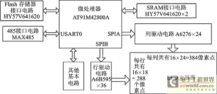
The hardware component block diagram of the system is shown in Figure 1. In Figure 1, the microprocessor is the AT91M42800A produced by Atmel, which uses the ARM7TDMI-based core.
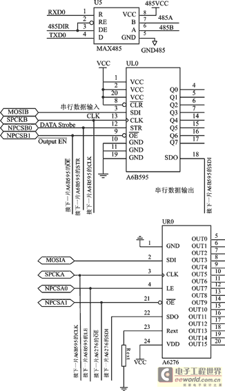
The high-performance 32-bit RISC architecture processor has a wealth of peripheral interface resources. The AT91M42800A has two USART peripheral interfaces. The system uses the USART0 port and MAX485 to form a 485 interface circuit. The specific interface circuit is shown in Figure 2. The AT91M42800A also has two SPI ports, each of which has four chip select signals, and can support 15 external devices through chip select. The system's approach is to connect the two SPI ports to the column driver circuit and the row driver circuit, and use the two chip select signals CS0 and CS1 to complete the signal latch and allow output control of the driver circuit. SPI CLK output As the clock signal input to the driver circuit, the operating frequency is 4 MHz.
The SRAM interface circuit consists of two HY57V641620 chips in parallel. The HY57V641620 is a 4 Banks × 1M × 16-bit SDRAM chip manufactured by Hynix. The single-chip HY57V641620 has a storage capacity of 4 groups × 16 M bits (8 MB) and supports automatic refresh. Bit data width. In order to fully utilize the data processing capability of the 32-bit CPU, the system uses two 8 ns HY57V641620 to form a 32-bit SDRAM memory system. The flash memory interface circuit consists of one HY29LV160 chip. HY57V641620 is a flash memory chip with a single-chip memory capacity of 16 M 2485 interface circuit, A6B595 and A6276 cascading circuit schematic bits (2 MB), 8/16-bit data width, and the system uses 16-bit data width mode of operation. Specific circuit connections can be found in reference [1].
The row driver circuit is composed of Allegro's 36 A6B595 cascades. The data lines of each row on the back of the display are cascaded into the shift register A6B595. The A6B595 integrates a driver composed of MOS transistors, which is enough to drive the LEDs. Glowing. The column driver circuit consists of 24 A6276 cascades from Allegro, which is a 16-bit serial-in and parallel-shift LED driver chip with latch. The pin and the connection method of the A6B595 and A6276 are connected as shown in Figure 2. The circuit is relatively simple (the corresponding port with the port frame labeled AT91M42800A). For detailed performance information, please refer to the related product documentation of Atmel and Allegro [2, 3]. The SPI port of the AT91M42800A uses a 16-bit serial output mode, which utilizes the high-speed performance of the 32-bit ARM processor to fully increase the data transfer speed.

Figure 1 system hardware block diagram

Figure 2 485 interface circuit, A6B595 and A6276 cascade circuit schematic
2 Working principle
The communication between the system and the host computer is completed by the USART0 port and 485 interface circuit of the AT91M42800A. The host computer only needs to transfer the data to be displayed to the AT91M42800A. After booting up, the AT91M42800A is initialized. After reading the startup code, the program code stored in the flash memory and the font data to be displayed are remapped into the SDRAM, so that the data access of the system is completed in the high-speed SDRAM. After receiving the data of the host computer, the data to be displayed by the AT91M42800A is converted into the corresponding LED screen display drive signal, and then the corresponding dynamic display effect control program is added (the screen is shifted to the left)
After moving up, opening, overwriting, blinking, and direct display, etc., the SPI port is separately output to the row and column drive circuits. At the same time, if necessary, the data or image picture transmitted by the host computer can also be saved in the flash memory.
The display adopts 1/16 dynamic sequential row scanning mode. Firstly, 24 bytes of data in the SPIA port are serially shifted into the corresponding 24 A6276 column driving circuits, and latched. Then, the SPIB port serially shifts the row and row strobe signals into the row driver circuit to complete the LED display of one row. Then, according to reason, each line of the LED screen is displayed one by one.
The duty cycle of the diode on and off time can be set by software to select the appropriate brightness to improve the life of the LED. The LED display screen actually installed in the field has an effective display area of ​​about 4.6 m2, which has 288×384=110 592 pixels. The minimum frame refresh time can be less than 8 ms, and the frame change frequency is above 125 Hz, which is more than the traditional single-chip microcomputer. The display system has increased the frame rate by more than 10 times, ensuring visual effects during dynamic display. At the same time, under the same conditions, the actual visible pixel points can also be increased.
3 Software section
The software of this system adopts μC/OSII operating system, which makes the system have powerful multi-task management, timer management, interrupt management, storage management and other functions. Through real-time monitoring of related registers, the stability of the system can be greatly improved. In the past, it could not be realized with a single-chip microcomputer and some DSP processors.
The display application uses the timer interrupt method. By setting an appropriate entry interrupt time constant, the LED refresh frame rate higher than 40 Hz can be obtained, so that the human eye can obtain a stable dynamic visual effect.
The real-time dynamic processing of the picture, that is, various dynamic display modes are written in the form of subroutines, each of which is an independent subroutine. The specific dynamic display modes include: moving the screen left and right, moving up and down, pulling the screen, covering, blinking, direct display and other methods.
4 Advantages of this system
1 Using a high-performance 32-bit RISC architecture ARM microprocessor, the hardware overcomes the shortcomings of the traditional 8/16-bit microcontroller in processing power, system architecture, addressing range and peripheral interface capabilities; the software uses real-time multitasking operating system The system has powerful management functions, real-time monitoring, complex program control, and program development and expansion. Compared with similar systems composed of single-chip microcomputers, the software stability and reliability of the system have been greatly improved.
2 This system eliminates the bus driver and decoding circuit of the LED display part in the traditional way. Unlike other single-chip systems, multi-processor is used to improve the display speed, dual-port RAM is used, or LED screen is divided into two. Multi-block solution. The system uses the SPI interface of the AT91M42800A to directly implement the LED display logic drive. It not only has a simple circuit, but also simplifies the software related programming, saving the GPIO hardware resources of the MCU.
3 AT91M42800A's SPI interface can use 16-bit transmission mode, coupled with A6276 high-speed 16-bit dedicated LED driver chip, so that the LED display screen speed is much higher than the traditional microcontroller.
Conclusion
The large-screen LED display system consisting of a 32-bit embedded RISC microprocessor, compared with the traditional 8/16-bit MCU-based LED display system, greatly improves performance without significantly increasing system cost. Compared with the display system adopting the DVI interface mode, the related circuit of the video processing is omitted, and the hardware structure is simple and the cost is low. By adopting the design scheme, the port resources of the single chip can be saved, the circuit structure of the display screen is effectively simplified, and the reliability of the entire display system is improved. The system has certain application value in the display of LED information such as monochrome video, animation and text. After a long-term actual operation on a large-scale logistics production line, it proved that the design scheme was successful.
Aluminium Deck Panel,Aluminium Wall Panel,Aluminum Grate Decking,Aluminum Plank Decking
KAM KIU ALUMINIUM GROUP , https://www.kamkiualuminium.com