Design of Inductive Communication System Based on FSK
introduction
The ocean is a treasure trove of human resources, rich in energy and minerals. With the continuous advancement of science and technology, the exploration and development of marine resources have also continued to deepen. The cable depth gauge is a tow cable depth positioning device used in the oil exploration process. It can control and position the underwater cable so that the detector in the cable receives the seismic wave returned by the air gun source. Induction communication based on FSK.
1 Development status of inductive communication
Underwater communication methods can be divided into: underwater acoustic communication, underwater laser and infrared communication, ultra-long wave communication, and induction communication. The disadvantages of underwater acoustic communication are slow transmission rate, small capacity, and poor anti-interference ability. In laser communication, plankton and mud on the seabed may cause temporary interruption of communication. The disadvantages of ultra-long wave communication are high power consumption and cost. Large; by comparison, the inductive communication method is simple to manufacture, inexpensive to manufacture, and insensitive to the surrounding environment. In consideration of power consumption, convenience and specific installation conditions, in the design process of the cable depth gauge, the inductive communication method is used for signal transmission.
The American manned submersible Alvin is a very famous manned submersible for deep sea exploration. Its sampler, chemical sensor, temperature detection, etc. all use electromagnetic coupling technology for signal transmission, and The application in multiple voyages is very successful. Foreign research and practical experience shows that electromagnetic coupling non-contact signal transmission technology is suitable for short-distance communication in deep sea environment.
In addition, foreign countries have developed inductive communication methods for marine seismic exploration towed line array products, which use bus address polling and broadcast communication methods, with a communication distance of up to several kilometers.
In China, a research institute has successfully applied inductive communication technology and developed a cable depth gauge for ocean exploration. Its communication distance, speed, and number of parallel nodes have great advantages. Verified in multiple probing operations. The communication part uses induction communication based on FSK modulation and demodulation.
2 Principles of inductive communication
According to the principle of electromagnetic induction, the change of current in the main coil will produce an alternating magnetic field around it. This alternating magnetic field causes the induced electromotive force of the secondary coil. Inductive communication uses this principle to work.
In inductive communication, because the signal is rapidly attenuated in proportion to the cubic power of the spatial distance, multiple communications within a short distance can achieve frequency division multiplexing without interference with each other.
Figure 1 is a schematic diagram of the system of the electromagnetic coupling signal transmission device. Since the communication mode is half-duplex, only the work process of transmitting data on the side of the cable depth detector is introduced: the demodulation adaptation circuit in the cable depth detector will sense After the coupled signal is filtered, amplified, balanced and shaped, it is demodulated and restored into communication data, and sent to the central controller in the given depth device. The controller performs corresponding operations according to the received data and instructions; when the cable depth device needs to upload data When it is given to the equipment on board, the communication data is modulated and sent to its internal induction device through the amplifier drive circuit. Through inductive coupling and signal processing, the control equipment on board can receive the data.
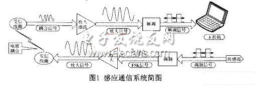
In the process of working, on the long-distance communication cable, multiple inductive nodes are connected in parallel at equal intervals. At this point, a cable depth gauge or other equipment is connected outside the cable. The magnetic bar coil is inductively coupled with the magnetic bar coil inside the cable sounder attached to the outside of the towline to transmit signals. The bus address polling and broadcast communication methods are used to realize the transmission of the ship's control equipment and multiple towed line arrays Between the data transmission, data transmission uses carrier communication technology to achieve several kilometers or even dozens of kilometers without relay transmission. The cable depth gauge is powered by the battery. After the battery is exhausted, the entire line array must be recovered and the battery in the depth gauge must be replaced.
3 Design of FSK modulation and demodulation part
3.1 Modulation unit design
The cable depth gauge used XR2206 as the modulation chip in the design process. XR2206 is composed of a voltage controlled oscillator (VCO), a current switch, a multiplier and a sine wave regulator. It is a monolithic integrated function generator that can generate high precision, high stability sine wave, square wave, sawtooth Wave and other waveform signals, the output signal can be controlled by the applied voltage, is an ideal FSK modulator chip, its internal block diagram shown in Figure 3.
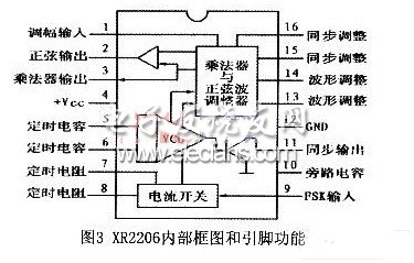
The working characteristics of XR2206: a. Voltage power supply 10 ~ 26V; b. Frequency temperature stability 20ppm / ℃; c. Frequency scanning range 2000: 1; d. Oscillation frequency is 0.01Hz ~ 1MHz; e. Sine wave distortion O. 5%; f. FSK keying level 1.4V; g. Sine wave output impedance 600Ω; h. Power consumption ≤750mW.
The modulator used for the cable depth gauge is shown in Figure 4.
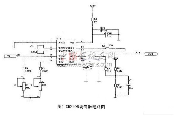
When using the XR2206 chip for frequency modulation, pin 1 is grounded, pin 9 is a digital level input pin, pin 2 is a signal output pin, and resistor R6 of pins 13 and 14 is used to adjust the distortion of the sine wave, and pin 3 is the multiplication The output end of the device and the sine wave regulator, the role of the connected resistor R7 is to adjust the output amplitude, that is, the amplitude of the output signal of pin 2 is proportional to the external resistance of pin 3. For the sine FSK waveform, Vout (pp) ≈0.6R7 (V ). The internal voltage-controlled oscillator VCO is actually a controllable oscillator whose output frequency is proportional to the input current. Its oscillation frequency depends on the timing capacitor and resistor. The VCO timing resistor has two pins that can be connected to ground. With two resistors, it is possible to provide two discrete output frequencies from pins 7 and 8 to easily form an FSK modulator. Set 9 feet as the high level corresponds to the output frequency f1 = 24.7kHz, when the low level corresponds to the output frequency f2 = 27.4kHz, baud rate fb = 2400b / s. Taking the timing capacitor C0 = 330pF, the timing resistance R1 = 1 / f1C0 = 122.68kΩ, R2 = 1 / f2C0 = 110.59kΩ can be calculated. Pins 13 and 14 are connected in series with 200Ω resistors to improve the output waveform.
3.2 Design of demodulation unit
The cable depth gauge uses XR221l as the core chip of the demodulation unit during the design process. It consists of a pre-amplifier, phase-locked loop PLL, phase detector, internal reference voltage source, and comparator. The VCO phase detector is used It forms a basic phase-locked loop with the external loop filter, and then with the FSK comparator, it can realize the FSK demodulation function. Its internal structure block diagram is shown as in Fig. 5.
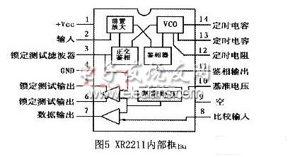
The working characteristics of XR2211: a. Working voltage range 4.5 ~ 20V: b. Operating frequency range O. 01Hz ~ 300kHz; c. Wide dynamic range 10mV ~ 3V; d. Frequency temperature stability Max = 50ppm / ℃.
In the peripheral circuit of XR2211, the carrier center frequency is 26kHz, the digital "1" modulation frequency is 24.7kHz, and the digital "O" modulation frequency is 27.4kHz. The transmission baud rate is 2400b / s, the relevant parameters of the peripheral circuit are determined according to the following formula, and the parameters are adjusted appropriately in actual application. a. Central oscillation frequency :; b. Timing resistance :; c. Timing capacitor: d. . The remaining parameters are selected as follows: R3 = 100kΩ; R4 = 510kΩ; C3 = 1nF; C6 = 10nF; R8 = 470kΩ. Among them, RO and C0 determine the center frequency f0 of the phase-locked loop, R2 determines the system bandwidth, C2 determines the phase-locked filter time constant and phase-locked damping factor, C3 and R3 form a first-order digital filter, and determine the output FSK waveform.
The frequency range of XR2206 is 0.01 ~ 1MHz, and the frequency range of XR2211 is 0.01 ~ 300kHz. When the two are used together, the carrier frequency of the modulator should be selected within the range of 0.01 ~ 300kHz. The signal at the modulation end is a constant amplitude FM signal with a peak value of 3V. When the two coils are close to each other, this signal is used to drive the sending coil. The coupling signal strength of the receiving coil is basically the same as the signal strength at the modulation end. The voltage range of the received signal of the demodulation chip XR2211 is 10mV ~ 3V. When the distance of the coil increases and the amplitude of the coupled electrical signal does not exceed this range, communication can still be guaranteed.
4 Summary and outlook
Because the working environment is underwater, it is not suitable for direct signal transmission through traditional cables. Especially in the case of deep sea high voltage, if the cable is torn, water will enter the carrying equipment through the gap of the wire, causing destructive or even catastrophic consequences Even if the cable is not broken, its entanglement with other objects may cause a series of failures. Therefore, non-contact signal transmission must be adopted to ensure safe and smooth underwater operation. The particularity of the working environment and working conditions under the sea requires the use of wireless signal transmission.
In addition, RS232, which is more commonly used in traditional wired communications, has a transmission rate of less than 20kb / s when the communication distance is less than 15m. When the communication distance is 100m, the communication rate is difficult to satisfy. The longest distance of the RS485 communication with more complete functions is only 1200m, and at most 32 communication nodes can be connected in parallel. When communicating in seawater, due to the worse channel environment, the communication distance, speed, and number of parallel nodes will be lower. Through the verification of CNOOC's multiple offshore operations, at present, the communication distance of induction communication can reach 6000m, the communication rate at this time is 2400b / s, the number of nodes that can be connected in parallel is up to 128, and the communication success rate is about 98%. Strong anti-interference ability. The advantages of inductive communication in terms of transmission distance and parallel nodes will play a more important role in the field of underwater communication.
Studying electromagnetic induction signal transmission technology will promote the development of China's ocean exploration capabilities and ocean science. At the same time, inductive wireless signal transmission technology also has great application potential in other short-range wireless communication occasions.
Frequency inverters for 3-phase asynchronous motors from 0.75 to 800 kW, variable torque applications
Transformer And Frequency Converter,3 Phase Inverter Air Conditioner,Inverter Vs Generator,Voltage And Frequency Converter
Wuxi Trenty Machinery & Equipment Co., Ltd. , https://www.elec-inverter.com