Frequency Conversion and Transmission--High Voltage Inverter Principle and Application
1 Introduction
This article refers to the address: http://
The motor is the main power-consuming equipment in industrial production. The application of high-voltage and high-power motors is more prominent, and most of these devices have great energy-saving potential. Therefore, it is necessary and urgent to develop high-voltage and high-power variable frequency speed control technology.
At present, with the rapid development of modern power electronics technology and microelectronic technology, high-voltage and high-power variable frequency speed control devices continue to mature, and the high voltage problem that has been difficult to solve has been solved in recent years by device series or unit series connection. . Its application fields and scope are also becoming more and more extensive, which provides technical prerequisites for industrial and mining enterprises to use energy (especially electric energy) efficiently and reasonably.
2. Analysis of main circuit of several common high-voltage inverters
(1) Unit series multiplexed voltage source type high voltage inverter
The unit series multi-voltage source type high-voltage inverter uses a low-voltage single-phase inverter in series to compensate for the lack of pressure capability of the power device IGBT. The so-called multiplexing means that each phase consists of several low-voltage power units connected in series. Each power unit is powered by a multi-winding phase-shifting isolating transformer, controlled by a high-speed microprocessor and driven by optical fiber isolation. However, it has the following disadvantages:
a) The number of power units and power devices used is too large. In the 6kV system, 150 power devices (90 diodes, 60 IGBTs) are used. The size of the device is too large, the weight is large, and the installation location and capital investment are problematic;
b) too many high-voltage cables are required, the internal resistance of the system is invisibly increased, the wiring is too much, and the fault point is correspondingly increased;
c) When a unit is damaged, the unit can be bypassed, but at this time, the voltage at the center point of the output voltage imbalance is floating, causing voltage and current imbalance, and thus the harmonics are correspondingly increased, and the motor will eventually lead to the motor. Damage
d) The output voltage waveform is fashionable at rated load, and the distortion is less than 25 Hz;
d) The output voltage waveform is fashionable at rated load, and the distortion is less than 25 Hz;
e) Due to the presence of transformers in the system, the system efficiency is not easy to achieve; in the phase shifting transformer, 6kV three-phase 6 winding × 3 (12 winding × 10 at 10kV) Yanbian delta connection, in the three-phase voltage imbalance ( In fact, when the three-phase voltage is impossible to be absolutely balanced, the internal circulation generated will inevitably cause an increase in internal resistance and a loss of current, and correspondingly increase the copper loss of the transformer. At this time, coupled with the inherent loss of the core of the transformer, the efficiency of the transformer will be reduced, which will affect the efficiency of the entire high-voltage inverter. This situation is more pronounced when the operation is lower than the rated load. At 10kV, the transformer has nearly 400 connectors and nearly 100 cables. Efficiency is up to 96% at rated load, but at light loads, efficiency is below 90%.
(2) Neutral point clamp three-level PWM inverter
This series of inverters adopts the traditional voltage type inverter structure. The inverter part of the neutral point clamped three-level PWM inverter adopts the traditional three-level mode, so the output waveform will inevitably produce relatively large harmonic components, which is inherent in the three-level inverter mode. . Therefore, an output LC filter must be configured on the output side of the inverter for use in ordinary squirrel cage motors. Also due to harmonics, the power factor, efficiency, and even life of the motor will be affected to some extent. Only at the rated operating point can the best working condition be achieved, but as the speed decreases, the power factor and efficiency will decrease accordingly. .
Multi-level + multiple high-voltage inverter. The multi-level + multiplexed high-voltage inverter is intended to solve the problem of limited voltage withstand voltage of high-voltage IGBTs, but this method not only increases the complexity of the system, but also reduces the multiplexed redundancy performance and the three-level structure. Simple advantages. Therefore, such a frequency converter is actually not desirable.
The performance price advantage of this type of frequency converter is not large. Instead of using multiple levels and multiple technologies at the same time, it is better to use the multiplexed inverter or three-level inverter of the high voltage IGBT mentioned above.
(3) Current source type high voltage inverter
The current source type high-voltage inverter in which the power devices are directly connected in series is formed by connecting a large inductance in series in the line, and directly connecting the SCR (or GTO, SGCT, etc.) power devices with slow switching speeds in series.
Although this method uses less power devices and is easier to control current, it does not really solve the series problem of high voltage power devices. Because even if the power device fails, due to the current limiting effect of the large inductor, the di/dt is limited, and the power device is not easily damaged, but the problem is serious pollution to the power grid and low power factor. Moreover, the current source type high-voltage inverter is sensitive to changes in the grid voltage and motor load, and cannot be made into a truly universal product.
The current source type high-voltage inverter is the earliest product, but wherever the voltage-type inverter arrives, it is forced to withdraw because it is obviously at a disadvantage in terms of economy and technology.
3. IGBT direct series direct high voltage inverter
3.1 Introduction to the main circuit
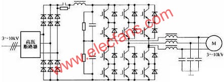
Figure 1. IGBT direct series high voltage conversion
As shown in Figure 1, the system in the figure is directly connected to the inverter through the high-voltage circuit breaker from the high voltage of the grid, through the high-voltage diode full-bridge rectification, DC smoothing reactor and capacitor filtering, and then inverter through the inverter, plus sine wave The filter realizes high-voltage variable frequency output simply and easily, and directly supplies the high voltage motor.
The two-level voltage type high-voltage inverter with power device IGBT directly connected in series is a kind of non-input and output transformer, IGBT direct series inverter and output efficiency successfully designed by using the mature technology of the inverter and using unique and simple control technology. Up to 98% of high-pressure speed control systems.
For applications requiring fast braking, a DC discharge brake is used, as shown in Figure 2:
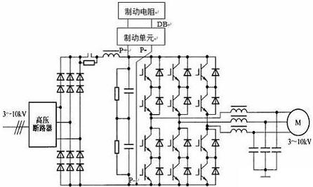
Figure 2. Main circuit diagram of IGBT direct series high-voltage inverter with DC discharge braking device
Features:
- With multi-core(2-8 core) design to fit with different industrial needs
- Design snap lock ensures stable and security firm
- Humanization design achieved blind operation
- Both soldering and crimpng are avaliable
- Socket and internal made of zinc alloy, with well protected eletromagnetic and radio frequency interference
- Gold-plated, high strength corrosion resistance and electrical conductivity
- Shell made of material PBT, Stable electrical performance, high strength and resistance to pressure, high temperature resistance, anti-explosion, anti-corrosive
- Both cable connector to cable connector and cable connector to panel mounting are available
Waterproof Harness,Dayton Wire Harness,Modernize Wiring Harness,American Auto Wire Harness
Dongguan YAC Electric Co,. LTD. , http://www.yacenter-cn.com