Traditional electrical engineering diagram into PLC ladder diagram programming process - Database & Sql Blog Articles
When designing a PLC program, the most common approach is to use an intuitive method. This means that the design relies heavily on the experience and understanding of the circuit designer, making it more subjective and direct. As a result, the process often involves trial and error, with the program being adjusted until it meets the desired function or action requirements. Because of this, each programmer may develop a different style, and the logic behind the code can be difficult for others—especially maintenance personnel—to understand. This makes the program less readable, even though programming itself is often seen as a straightforward task. However, in many workshop manuals, this aspect is rarely discussed in detail.
To illustrate this point, let's take the example of a "three-phase induction motor fault alarm control" circuit. We'll walk through the process of converting a traditional electrician diagram into a ladder diagram and discuss the programming steps involved. I believe that even if you're familiar with loop conversions or basic programming, this explanation might still offer some new insights.
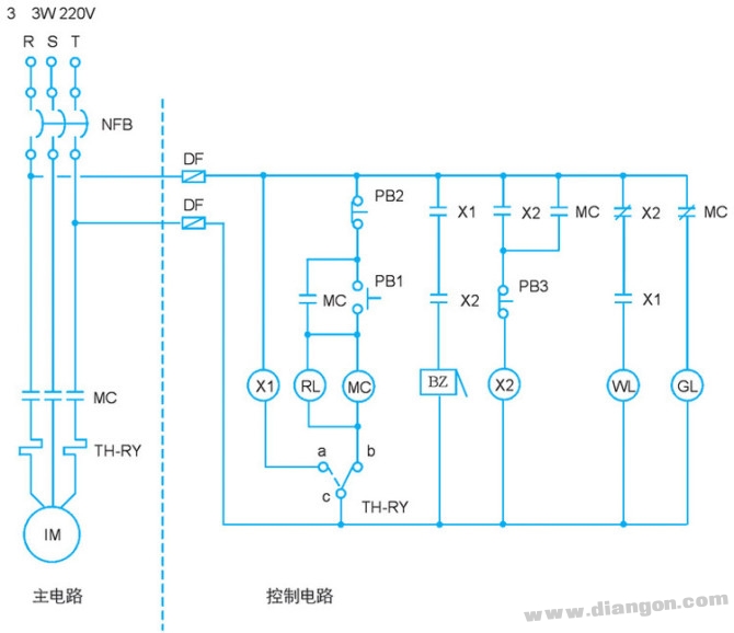
Figure 1: Three-phase induction motor fault alarm control circuit diagram
Action Description:
- When power is normal, only the green light (GL) is on, and the motor does not operate.
- Pressing the start button (PB1) activates the electromagnetic contactor (MC), which starts the motor and turns on the red light (RL), while the green light (GL) turns off.
- Pressing the stop button (PB2) deactivates the contactor (MC), stopping the motor and turning off RL, while GL lights up again.
- If the motor overheats or experiences a fault, the thermal relay (TH-RY) activates, stopping the motor, triggering the buzzer (BZ), turning off RL, and turning on GL.
- Pressing PB3 stops the alarm, turns on the white light (WL), keeps GL on, and turns off RL.
- After troubleshooting, resetting the thermal relay allows the motor to restart, with WL turning off, GL lighting up, and RL going out.
Step 1: I/O Encoding
The first step in converting a traditional electrician diagram to a ladder diagram is I/O encoding. This involves identifying the input and output components from the original diagram and mapping them to corresponding PLC terminals. For example, external switches may be wired as normally open (NO) or normally closed (NC) contacts, as shown in Table 1.
Step 2: PLC External Wiring Diagram
Once the I/O is encoded, the next step is to draw the PLC external wiring diagram. The wiring typically uses NPN-type connections, where the 24V terminal is connected to the S/S terminal, as illustrated in Figure 2.
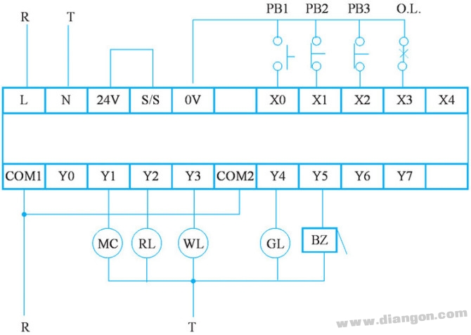
Figure 2: PLC external wiring diagram
Step 3: Converting to Ladder Diagram
The next step is to convert the electrician diagram into a ladder diagram. This requires repositioning the contacts and coils to match the structure of the PLC ladder logic. In the original diagram, contacts are usually before the coil, so the diagram must be redrawn accordingly. After redrawing, the layout should look like Figure 3.
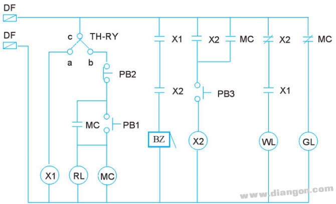
Figure 3: Redrawn electrician diagram
Step 4: Replacing Components with I/O Codes
Now, replace the input/output components in the diagram with their respective I/O codes. For instance, the TH-RY and CB contacts should be treated as independent control loops, as shown in Figure 4.
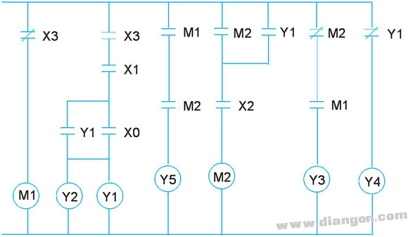
Figure 4: I/O coded electrician diagram
Step 5: Flipping and Adjusting the Diagram
Next, rotate the diagram 90 degrees to the left and then flip it vertically to create the ladder diagram. However, adjustments are needed because the PLC ladder diagram has specific formatting rules. For example, Y1 and X0 contacts, as well as output coils Y1 and Y2, must be properly aligned, as shown in Figure 5.
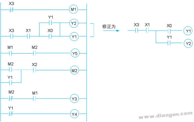
Figure 5: Adjusted stepped diagram
Tip: If using Visio, rotating the diagram 90° to the left and flipping it vertically can make this process much easier.
Step 6: Final Ladder Diagram
Once the adjustments are made, the final ladder diagram drawn using PLC programming software will match the corrected stepped diagram, as shown in Figure 6.
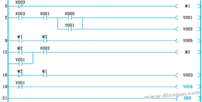
Figure 6: Ladder diagram from programming software
Step 7: Converting to Instructions
Finally, the ladder diagram can be converted into actual PLC instructions, as shown in Figure 7.
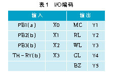
Figure 7: Instruction conversion
Step 8: Complete PLC Conversion
With the I/O wiring and ladder diagram completed, the traditional electrician system can now be fully replaced by a PLC-based system. The hardware wiring is replaced by the software program, as shown in Figure 8.
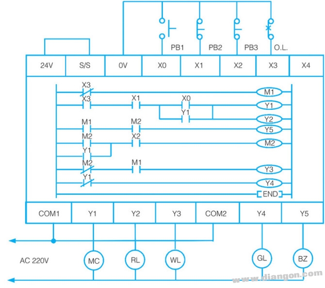
Figure 8: PLC replacement after hardware wiring
Conclusion:
The main goal of PLC development is to replace traditional relay-based sequential control systems. By using software instead of physical wiring, control sequences can be easily modified without changing the hardware. Most PLCs are built based on traditional relay control circuits, with relays represented as symbols in ladder diagrams or instruction sets. However, the resulting control logic is still influenced by the designer’s personal experience, making it subjective and sometimes hard to follow for others. This lack of readability is one of the challenges in PLC programming, despite its efficiency and flexibility.
ZOOKE provides you with safe and reliable connector products, with 5.7 spacing products providing more possibilities for limited space and creating more value for the research and development and production of terminal products.
5.70 wire to board connectors,5.7 connectors,ZOOKE connectors
Zooke Connectors Co., Ltd. , https://www.zooke.com