Design of a Video Remote Control Car Based on STM32 Microcontroller
With the continuous advancement of science and technology, automation has become more sophisticated, and intelligent remote control systems are now being applied across various industries. The development of robotic cars is a key part of mobile robotics, integrating multiple technologies such as computer science, sensing, and communication. These vehicles are designed to recognize paths and control speed and direction using wireless network video technology.
The car in this project uses an STM32 microcontroller as its main processor and relies on a Wi-Fi RF module, the RT5350, to transmit real-time video. This project involves a wide range of technical areas, including MCU programming, OpenWrt router configuration, and Windows-based software development. The implementation of the video-controlled car is divided into three levels:
1. **The underlying driver layer**: This layer is responsible for controlling the movement of the car’s motors and the camera’s pan/tilt mechanism. Since the STM32 microcontroller alone cannot provide enough current to drive the motors, a motor driver module is necessary. In this project, the L298N motor driver is used to control the DC motors of the vehicle.
2. **The middle transport layer**: This layer handles the transmission of control commands and video streams via the RT5350 router platform. It ensures that data flows smoothly between the remote control interface and the car.
3. **The top-level control layer**: This layer runs on a Windows-based system, allowing users to interact with and control the car remotely through a graphical user interface.
**1.1 Motor Drive Principle**
The car has two DC motors connected to the left and right wheels. The direction of each motor—forward, backward, or stopped—is determined by the signals sent from the STM32 microcontroller. The four control lines (IN1–IN4) of the STM32 are connected to the corresponding input pins of the L298N, while the PWM signal lines (ENA and ENB) control the motor speed. A detailed circuit diagram is shown in Figure 1.
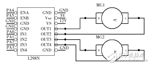
Figure 1: Circuit schematic
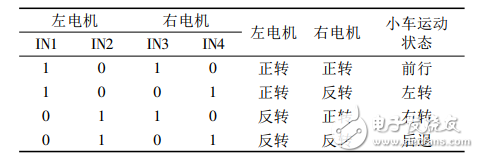
The IN1 and IN2 pins control Motor A, which is connected to OUT1 and OUT2. Similarly, IN3 and IN4 control Motor B. The motion modes of the car are determined by the combination of these inputs, as shown in Table 1.Table 1: Corresponding motion modes of the car
3.2v12-30Ah Lithium Battery Cells
3.2v12-30Ah Lithium Battery Cells,3.2v12-30Ah Lithium Battery Cells price,3.2v12-30Ah Lithium Battery Cells product
Jiangsu Zhitai New Energy Technology Co.,Ltd , https://www.zttall.com