Lithium battery protection board principle
The reason why lithium batteries (fillable) need protection is determined by its own characteristics. Because the material of the lithium battery itself determines that it can not be overcharged, overdischarged, overcurrent, short circuited and ultra-high temperature charge and discharge, the lithium battery lithium battery assembly will always follow an exquisite protection board and a current fuse.
The protection function of the lithium battery is usually completed by the protection circuit board and the current device such as the PTC. The protection board is composed of electronic circuits, and the voltage of the battery core and the charging and discharging circuit are accurately monitored at -40 ° C to +85 ° C environment. Current, timely control of the current circuit on and off; PTC in the high temperature environment to prevent battery damage.
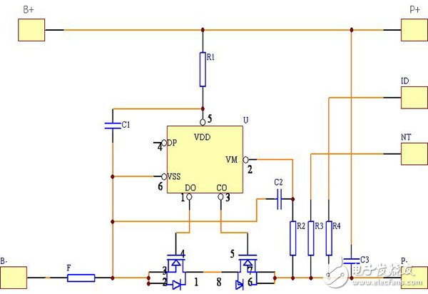
Ordinary lithium battery protection boards usually include control ICs, MOS switches, resistors, capacitors, and auxiliary devices FUSE, PTC, NTC, ID, memory, and so on. The control IC controls the MOS switch to be turned on under all normal conditions, so that the cell and the external circuit are turned on, and when the cell voltage or the loop current exceeds a prescribed value, it immediately controls the MOS switch to turn off, and protects the cell. Safety.
When the protection board is normal, Vdd is high level, Vss, VM is low level, DO and CO are high level. When any parameter of Vdd, Vss, VM is changed, the level of DO or CO will be A change has occurred.
1. Overcharge detection voltage: In the normal state, Vdd gradually rises to the voltage between VDD and VSS when the CO terminal changes from a high level to a low level.
2. Overcharge release voltage: In the state of charge, Vdd gradually decreases to the voltage between VDD and VSS when the CO terminal changes from low level to high level.
3. Overdischarge detection voltage: In the normal state, Vdd gradually decreases to the voltage between VDD and VSS when the DO terminal changes from high level to low level.
4. Overdischarge release voltage: In the overdischarge state, Vdd gradually rises to the voltage between VDD and VSS when the DO terminal changes from low level to high level.
5. Overcurrent 1 detection voltage: In the normal state, the VM gradually rises to the voltage between VM and VSS when DO changes from high level to low level.
6. Overcurrent 2 detection voltage: In the normal state, the VM rises from OV at a speed of 1 ms or more and 4 ms or less to the voltage between VM and VSS when the DO terminal changes from a high level to a low level.
7. Load short-circuit detection voltage: In the normal state, the VM rises at a speed of 1 μS or more and 50 μS or less from OV to the voltage between VM and VSS when the DO terminal changes from a high level to a low level.
8. Charger detection voltage: In the overdischarge state, the VM gradually drops to OV and the VM-VSS voltage changes from low level to high level.
9. Current consumption during normal operation: In the normal state, the current flowing through the VDD terminal (IDD) is the current consumption during normal operation.
10. Over-discharge current consumption: In the discharge state, the current flowing through the VDD terminal (IDD) is the over-current discharge current consumption.
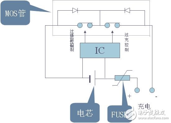
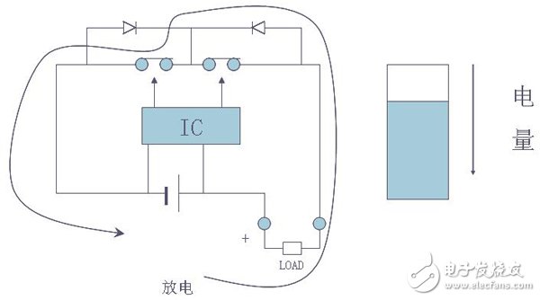
1. Normal state: The battery voltage is above the overdischarge detection voltage (2.75V or more), the overcharge detection voltage is below (4.3V or less), and the voltage of the VM terminal is above the charger detection voltage. Overcurrent/detection When the voltage is below (OV), the IC controls the MOS transistor by monitoring the voltage difference between VDD and VSS and the voltage difference between VM and VSS. The DO and CO terminals are both high and the MOS transistor is turned on. At this time, you can charge and discharge freely;
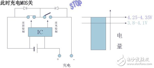
When the battery is charged so that the voltage exceeds the set value VC (4.25-4.35V), VD1 flips to make Cout low, T1 is turned off, charging stops, and when the battery voltage falls back to VCR (3.8-4.1V), Cout It goes high, T1 turns on and continues to charge, VCR is less than a fixed value of VC to prevent the current from jumping frequently.
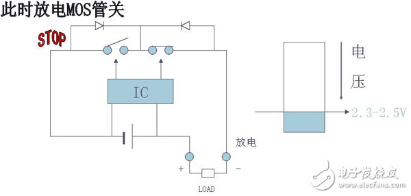
When the battery voltage drops to the set value VD (2.3-2.5V) due to discharge, VD2 flips, and after a short time delay fixed inside the IC, Dout becomes low level, T2 is turned off, and discharge stops.


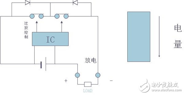
When the circuit discharge current exceeds the set value or the output is short-circuited, the overcurrent and short circuit detection circuits operate to turn off the MOS transistor (T2) and the current is turned off.
The protection loop consists of two MOSFETs (T1, T2) and a control IC (N1) plus some RC components. control
The IC is responsible for monitoring the battery voltage and the loop current, and controlling the gates of the two MOSFETs. The MOSFET functions as a switch in the circuit to control the conduction and shutdown of the charging circuit and the discharging circuit, respectively, and C2 is a time delay capacitor. The circuit has Overcharge protection, over discharge protection, over current protection
Protection and short circuit protection function, its working principle is analyzed as follows:
1, normal state
In the normal state, the "CO" and "DO" pins of N1 output high voltage in the circuit, both MOSFETs are in conduction state, and the battery can be freely charged and discharged. Since the on-resistance of the MOSFET is small, it is usually smaller. 30 milliohms, so its on-resistance has little effect on the performance of the circuit.
The current consumption of the protection circuit in this state is μA level, usually less than 7μA.
2, overcharge protection
Lithium-ion batteries require a constant current/constant voltage. In the initial stage of charging, they are charged at a constant current. As the charging process, the voltage rises to 4.2V. (Depending on the cathode material, some batteries require a constant voltage of 4.1V.) ), switch to constant voltage charging until the current is getting smaller and smaller.
When the battery is being charged, if the charger circuit loses control, the battery voltage will exceed 4.2V and continue constant current charging. At this time, the battery voltage will continue to rise. When the battery voltage is charged to over 4.3V, the battery chemistry Side effects will increase, causing battery damage or safety issues.
In a battery with a protection circuit, when the control IC detects that the battery voltage reaches 4.28V (this value is determined by the control IC and different ICs have different values), the "CO" pin will be converted from a high voltage to a zero voltage. Turning T1 from on to off, thus cutting off the charging circuit, so that the charger can no longer charge the battery, which acts as an overcharge protection. At this time, due to the presence of the body diode VD1 that is provided by the T1, the battery can discharge the external load through the diode.
There is still a delay time between when the control IC detects that the battery voltage exceeds 4.28V and when the T1 signal is turned off. The length of the delay time is determined by C2, and is usually set to about 1 second to avoid the error caused by the interference. judgment.
3, over discharge protection
When the battery is discharged to the external load, its voltage will gradually decrease with the discharge process. When the battery voltage drops to 2.5V, its capacity has been completely discharged. At this time, if the battery continues to discharge the load, it will cause the battery. Permanent damage.
During the battery discharge, when the control IC detects that the battery voltage is lower than 2.3V (this value is determined by the control IC, different ICs have different values), the "DO" pin will be converted from high voltage to zero voltage, making T2 Turning from conduction to shutdown, the discharge circuit is cut off, so that the battery can no longer discharge the load, which acts as an over-discharge protection. At this time, due to the presence of the body diode VD2 that is provided by the T2, the charger can charge the battery through the diode.
Since the battery voltage can no longer be lowered under the over-discharge protection state, the current consumption of the protection circuit is required to be extremely small. At this time, the control IC will enter a low-power state, and the entire protection circuit consumes less than 0.1 μA. There is also a delay between the time when the control IC detects that the battery voltage is lower than 2.3V and the signal that turns off the T2. The length of the delay time is determined by C2, usually set to about 100 milliseconds to avoid errors caused by interference. judgment.
4, over current protection
Due to the chemical characteristics of lithium-ion batteries, battery manufacturers stipulate that their discharge current should not exceed 2C (C=battery capacity/hour). When the battery exceeds 2C current discharge, it will cause permanent damage or safety problems.
During the normal discharge of the battery, the discharge current is passed through two MOSFETs in series. Due to the on-resistance of the MOSFET, a voltage is generated across the MOSFET. The voltage value U=I*RDS*2, RDS is a single MOSFET on-resistance, the “V-†pin on the control IC detects the voltage value. If the load is abnormal for some reason, the loop current increases, and when the loop current is so large that U>0.1V (this value is When the control IC determines that different ICs have different values, the "DO" pin will be converted from a high voltage to a zero voltage, causing T2 to turn from on to off, thereby cutting off the discharge loop and causing zero current in the loop. It acts as an overcurrent protection.
There is also a delay time between when the control IC detects an overcurrent and when the T2 signal is turned off. The length of the delay is determined by C2, usually about 13 milliseconds, to avoid misjudgment caused by interference.
In the above control process, the overcurrent detection value depends not only on the control value of the control IC, but also on the on-resistance of the MOSFET. When the MOSFET on-resistance is larger, the over-current protection is applied to the same control IC. The smaller the value.
5, short circuit protection
When the battery is discharging to the load, if the loop current is so large that U>0.9V (this value is determined by the control IC and different ICs have different values), the control IC determines that the load is short-circuited, and its “DO†pin will It quickly turns from a high voltage to a zero voltage, turning T2 from on to off, thereby cutting off the discharge loop and providing short-circuit protection. The short-circuit protection has a very short delay time, usually less than 7 microseconds. Its working principle is similar to overcurrent protection, except that the judgment method is different, and the protection delay time is also different.
| About Paper Covered Flat Aluminium Wire |
Paper wrapped winding wire is made up of bare from oxygen free Copper Rod or electrical aluminum rod by drawing or extruding processing and wrapped by insulation materials.paper covered single wire , with insulation wrapping in the outside layer
As per Conductor Material:Copper , aluminum
As per Inner Conductor: Paper wrapped bare
Insulation thickness:Double paper covered (DPC) orTriple Paper Covered (TPC) ,According to Customer`s requirements
Packaging DetailsInner packing : Wooden bobbin
Outer packing : Wooden pallet and stretch film
Or according to our custormers' requirements

Production Scope
Conductor of Paper wrapped wire
Bare Wire Round Wire:Φ1.00 mm-Φ5.00 mm
Rectangular Wire thickness a:1.00 mm-5.60 mm
Width b:2.00 mm-16.00 mm
Conductor of Composite wires
Max wrapping layers once: 24 layers for Paper Covered Wire
4 layers per wire and 16 layers outside for composite wires
We could offer products of special requirements on conductor size, insulation layer thickness, or wire number of the composite.
Paper Covered Flat Aluminium Wire
Electrical Wire,Paper Covered Flat Aluminium Wire,Covered Magnet Aluminum Wire,Covered Magnet Aluminum Winding
HENAN HUAYANG ELECTRICAL TECHNOLOGY GROUP CO.,LTD , https://www.huaonwire.com