Accelerate the design of Bluetooth® connectivity for IoT applications
Before discussing the ATBTLC1000-XPro Bluetooth Low Energy® expansion board, let's take a quick look at the ATBTLC1000 wireless microcontroller used in the board. The SoC device consists of an ARM Cortex-M0 microcontroller, a 2.4 GHz wireless transceiver, 128 kB RAM, 128 kB ROM, and AES-128 and SHA-256 hardware accelerometers. In addition, the device provides a full range of GPIO and serial master/slave SPI, I2C master/slave and UART interface connections. The device combines an integrated DC/DC converter with a Power Management Unit (PMU) to help the SoC implement many ultra-low power specification modes. It also includes a single 11-bit ADC, four PWM ports, and a general purpose timer. In addition, the ROM is used to store the appropriate Smart Bluetooth protocol stack (Bluetooth 4.1), including the L2CAP service layer protocol, security manager, attribute protocol (ATT), common attribute protocol (GATT), and universal access specification (GAP). Application specific specifications include proximity, thermometer, heart rate and blood pressure. Figure 1 shows a block diagram of this SoC device.
The device is capable of operating from a 1.8 to 4.3 VDC battery. When using a 3.6 V supply, the current consumed in sleep mode while maintaining RAM and RTC operation is as low as 1.1 μA, and the peak current is 4.0 mA in receive mode.
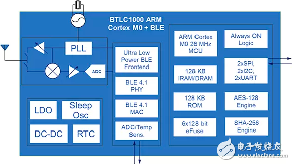
Figure 1: Block diagram of the ATBTLC1000.
Many IoT applications will require fewer battery replacements during battery-powered devices. The suburban environment is usually not very convenient. It may not be very far away or it may be dangerous. When using IoT sensors in these places, it usually causes high cost due to short battery life and potential damage to the sensor manufacturer's brand. With an innovative power architecture, the ATBTLC1000 eliminates the need for external regulators and off-chip components. The PMU block is typically 83% energy efficient, including a DC/DC buck converter and a low dropout regulator (LDO) that converts battery voltage to power the BLE core and RF transceiver.
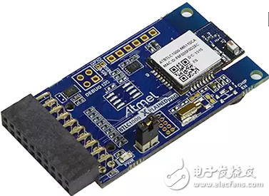
Figure 2: Atmel ATBTLC1000 Xplained Pro expansion board.
For example, starting with a new microcontroller-based design, Atmel's Xplained Pro board series is an ultra-fast, ultra-convenient approach. The Xplained Pro board is powered by Atmel Studio, Atmel's integrated development environment platform, with Atmel Software Framework (ASF), full board support drivers, code examples and documentation, and all of Atmel's AVR and ARM-based microcontroller product families are available. The board. As shown in Figure 2, the ATBTLC1000 expansion board uses a standard connector header to easily combine various forms of connectivity, including wired and wireless, capacitive touch control, extended IO, and a range of MEMS-based sensors. The design takes into account the needs of the engineer, not only allows engineers to speed up the time to market, but also provides engineers with more confidence in design by providing complete documentation and application notes for each board.
The ATBTLC1000 Xplained Pro incorporates FCC and ETSI pre-certified wireless SoCs, digital temperature sensors, debugger header support (UART, I2C, and ammeter) and a 32 kHz crystal in a modular package. It can be connected to multiple host MCU Xplained Pro boards. To simplify processing, the expansion board and Atmel SAML21 Xplained Pro board are available as a complete kit, or you can purchase the MCU board separately.
Getting started with any Xplained Pro platform is extremely simple. You need to download Atmel Studio (currently version 7) for free from the Atmel website before you start. The downloaded package includes the Atmel Software Framework, so you can always use the code samples. Once installed, launch Atmel Studio and connect the expansion board to your microcontroller board. Atmel Studio automatically detects which MCU and expansion board are connected and displays the login page for that combination. The login page provides documentation and specifications for you to choose to launch the Atmel Software Framework to access the sample application.
As mentioned earlier, the ATBTLC1000 SoC has an intelligent Bluetooth link controller that causes the host microcontroller to perform all standard Bluetooth server and client operations such as GAP and GATT. The SoC provides all BLE 4.1 link layer and application specification features through on-chip firmware. Atmel provides an adapter API to communicate with the link layer firmware.
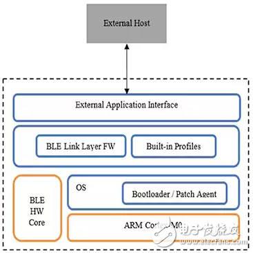
Figure 3: ATBTLC1000 intelligent link controller host connection diagram.
Atmel's API uses a direct programming model that typically includes three operational groups, platform/link controller initialization, device configuration, and event processing and monitoring. Figure 4 shows a simple application flow chart. The at_ble-init() function call starts the link controller. Device configuration is then required to set the device address and name any relevant advertising data. The API uses a request and response mechanism. An API call can trigger one or more event messages and return to the calling application. A complete list of available APIs can be found in Atmel's Bluetooth Low Energy API: Software Development User Guide 1 and Atmel Software Framework 2.
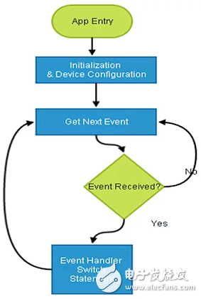
Figure 4: API programming model – application flow.
A plan diagram is a perfect example of how the API works: Figure 5. In this example, the process of setting up a GAP advertisement means that the peripheral will wirelessly send a one-way broadcast data for another Bluetooth device to discover. In addition to this required advertising data, such as device name and ID, other information that can be communicated can help establish a connection.
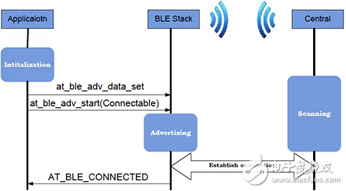
Figure 5: GAP advertising process plan diagram.
This other data is the call response data. After the function at_ble-init() is initialized, the ad data needs to be set in the at_ble_adv_data_set function before making a call to the ad function. If the purpose is to advertise and then establish a connection, then call at_ble_adv_start (connectable). The code example in Figure 6 shows only the first part of the application that started the process, from defining and setting the device name, initializing the device, setting up ad response data, to starting the ad. This is just a simplistic example of using the Atmel Bluetooth API when designing an application.
Wire Carrier & Tubular Carriers
Fabricated steel wire baskets and wire carriers are designed and manufactured using high quality steel tubing as well as sheet metal for the coiling of wire. A solid basket is often used in house for rod break-down and then used subsequently in wire drawing of large stranders for power cables. Wire carriers are used for coiling and packaging wire from wire drawing equipment, and are then used as in-house or shipping packages.
Wire Coiling Baskets
- Manufactured from high quality tubing
- Heavy duty construction
- Heavy duty construction
- Various sizes per application
- Standard sizes per coiler
- Manufactured from high quality tubing
- Light-to-heavy duty constructions
- Square, clover & star base
- Sizes as per request
Wire Carrier

Wire Carrier
Coil Carriers, Cable Basket, Steel Basket, Steel Coiler, Wire Carrier
NINGBO BEILUN TIAOYUE MACHINE CO., LTD. , https://www.spool-manufacturer.com