Select bidirectional converter control scheme
The 48V-12V dual battery power system is widely used in mild hybrid electric vehicles. Dynamic operating conditions of the vehicle may require up to 10 kW of electrical power to be transferred back and forth between the two battery rails. Since the running vehicle is operating in a variety of situations, real-time control of power flow requirements in one direction or the other is a fairly complex task requiring intelligent control of its digital control scheme. As a result, when leading automotive manufacturers and Tier 1 suppliers began developing 48V-12V bidirectional power converters, most used an all-digital approach.
All digital solutions are expensive because they require many discrete analog circuits. These analog circuits include precision current sense amplifiers, power MOSFET gate drivers, monitoring and protection circuits, and more. Discrete solutions are cumbersome and not reliable due to the large number of devices on the board. To reduce solution size and cost, while improving performance and system-level reliability, some Tier 1 vendors are looking for a hybrid architecture with microcontrollers handling higher levels of intelligent management and highly integrated analog controllers. Implement the power converter stage. This blog post will discuss how to determine the most appropriate control scheme for this analog controller.
Table 1 summarizes the advantages and disadvantages of different control schemes.
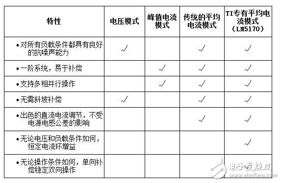
Table 1: Comparison of control schemes
A48V-12V bidirectional converters typically must have high precision current regulation (better than 3%) to accurately control the amount of power transferred from one battery rail to another. Due to the high power, systems typically require multiphase circuits in interleaved parallel operation to share the total load, and the sharing should be balanced between the phases. Therefore, the voltage control mode is not suitable because it cannot achieve multi-phase sharing.
A peak current mode control scheme that generates a pulse width modulation (PWM) signal based on the peak value of the inductor current enables multiphase sharing. However, the sharing balance is largely affected by the tolerance of the power inductor. Power inductors typically have tolerances of ±10% and result in significant sharing errors, resulting in unbalanced power dissipation for different phases. To make matters worse, the peak current of the inductor has an inherent error with the DC current, resulting in less accurate current regulation, which in turn leads to less accurate power delivery.
The traditional average current mode control scheme solves the current error problem of peak current mode control because it regulates the average inductor current and eliminates the effects of inductance tolerance on current regulation. However, power plant transfer functions vary with operating voltage and current conditions, and two-way operation requires two different loop compensations.
To overcome the challenges of conventional average current mode control schemes and simplify practical circuit implementations, TI has developed an innovative average current mode control scheme for 48V-12V bidirectional converter operation, as shown in Figure 1 and Table 1. Power levels include:
· High side FET (Q1).
· Low side FET (Q2).
· Power inductor (Lm).
· Current sense resistor (Rcs).
· Two batteries, one on the HV port and the other on the LV port.
The control circuit includes:
• A current-sense amplifier with a gain of 50, directional steering by direction command DIR (“0†or “1â€).
• The transconductance amplifier is used as a current loop error amplifier with a reference signal (ISET) applied to the non-inverting pin to set the phase DC current regulation.
· PWM comparator.
· A ramp signal proportional to the HV-Port voltage.
• A DIR controlled steering circuit for applying a PWM signal to control Q1 or Q2 as the main switch.
· A loop compensation network at the COMP node.
Rcs senses the inductor current and the signal is amplified 50 times. This signal is sent to the inverting input of the transconductance amplifier, resulting in an error signal at the COMP node, which is also the node of the non-inverting input of the PWM comparator. The comparison error signal and the ramp signal generate a PWM signal. Controlled by the DIR command, the PWM signal controls Q1 for buck mode operation and forces current from the HV port to the LV port or reverses the direction of current flow when sent to Q2.

Figure 1: Bidirectional current converter for TI's dedicated average current mode control scheme 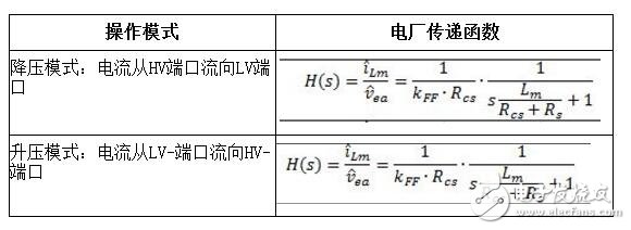
Table 2: Converter power device transfer function (KFF is the ramp generator coefficient; Vramp = KFF & TImes; VHV-port; Rs is the effective total resistance along the power flow path, excluding Rcs)
Table 2 shows the advantages of the new control scheme. The power plant transfer function is the same for two-way operation, it is a first-order system. In addition, the transfer function is independent of operating conditions such as port voltage and load current levels. Therefore, the application of a single Type II compensation network will always stabilize the bidirectional converter under all operating conditions, greatly simplifying the use of actual circuits and improving performance.
TI's proprietary average current mode control scheme is suitable for automotive 48V-12V bidirectional current controllers. It requires a single Type II compensation network to cover bidirectional operation without having to consider operating conditions. Current Regulation Accuracy - Despite the presence of inductance tolerances, even sharing of high power, multiphase parallel operation, etc. - will greatly simplify the design of high performance bidirectional converters. TI implemented this control scheme in the LM5170-Q1 multiphase bidirectional current controller. Read the blog post "Battery 48V and 12V Power Interconnects in a Dual Battery System" to learn how to overcome the challenge of designing a hybrid electric vehicle power supply.
- USB-C Hub (5-in-1): Extend one 4K UHD HDMI port, two supper speed USB 3.0 ports, one SD menmory card slot and one TF momory card slot from one USB-C/thunderbolt 3/ type c port
- 4K Video USB-C To HDMI Adapter: Mirror or extend your screen with USB C Hub HDMI port and directly stream 4K UHD @ 30Hz or Full HD 1080p video to HDTV, monitor or projector
- Super Speed USB 3.0 Ports(At Full-Speed): Allow you to connect keyboard, mouse, hard drive,etc to MacBook Pro,Up to 5Gbps data transmission speed, down compatible with USB A 2.0 and below. Because HDD/SDD needs more power, so this adapter only allow connect 1 HDD/SSD
- Convinient USB-C To Card reader for USB-C/Type-C/Thunderbolt 3 devices to access files from SD/TF card reader, perfect for Photographer or designer,etc
- Aluminiun Case Design(Space Gray), Perfect for New laptops with USB-C Port, such as 2017 Macbook Pro,2015/2016 Retain 12 inch Macbook, Dell XPS 13, HP Spetre X2, etc.
Hdmi Adapter,Connect Adapter,Hd Adapter,Electrical Adapters
CHANGZHOU LESEN ELECTRONICS TECHNOLOGY CO.,LTD , https://www.china-lesencable.com