Solution Analysis of Extending Monitor Battery Life Based on Micropower IC
This article describes a low-power heart rate monitor (HRM) that utilizes a micropower IC. First, the definition of HRM will be given, and the analog front end will be introduced, including the main signal chain and other circuits used to implement special functions; then a method for designing the FIR (Digital Finite Impulse Response) filter will be provided; finally, the display will be The experimental results of HRM include the accuracy of heart rate calculation and the power consumption of HRM.
Many factors determine that patient monitoring devices require low voltage and low power operation, requiring low power, high precision IC devices. One factor is the continued use of batteries: in Holter monitors and other portable mobile electrocardiogram (ECG) systems, batteries have been in use for decades. As the sole power source, the low voltage battery ensures that the patient (and equipment) does not come into contact with high supply voltages under fault conditions, so low power ICs must be used to extend battery life. Another decisive factor affecting healthcare ICs is that the market demands more functionality without adding space, power or cost.
This article describes a low-power heart rate monitor (HRM) that utilizes a micropower IC. First, the definition of HRM will be given, and the analog front end will be introduced, including the main signal chain and other circuits used to implement special functions; then a method for designing the FIR (Digital Finite Impulse Response) filter will be provided; finally, the display will be The experimental results of HRM include the accuracy of heart rate calculation and the power consumption of HRM.
Heart rate monitor (HRM)HRM is a personal monitoring device that patients can use to measure heart rate in real time or record it for later research. The main function of HRM is to calculate the heart rate and display the ECG waveform. In addition, lead-off detection should be provided. HRMs are typically portable devices that are battery powered, so power consumption must be low.
In the design presented in this paper, the analog front end of the HRM is built using the following devices: a micropower instrumentation amplifier, an operational amplifier, and a microconverter with a 12-bit ADC, sample-and-hold amplifier, and digital processor. The processed data is sent to the PC for display.
HRM analog front endFigure 1 shows the system block diagram of the design. Micropower instrumentation amplifiers form an excellent HRM input amplifier with high power consumption, small size, high common-mode rejection ratio (CMMR), rail-to-rail input and output over the entire frequency range, and are ideal for this application. The skin potential is between 0.2mV and 2mV. The high performance micropower instrumentation amplifier solves many common human skin potential measurement problems. For this application, the best instrumentation amplifier should have a high CMMR to reject common mode signals such as line noise or high frequency EMI in operating room equipment. It should also have rail-to-rail output characteristics to provide a wide dynamic range, providing higher gains that are difficult to achieve with typical instrumentation amplifiers. In addition, when using a series input resistor before a micropower instrumentation amplifier (for example, Analog Devices' AD8236), the designer should configure the RC filter to reduce high frequency noise.
The micropower instrumentation amplifier is followed by an integrator feedback network. The network is implemented with a 4.7μF capacitor and a 100kΩ resistor to set the -3dB cutoff frequency of the high-pass filter. It can suppress any differential DC offset that may be generated by the electrode's half-cell overpotential.
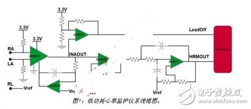
The micropower op amp provides 13 times more gain for amplifying weak signals. An active second-order low-pass Bessel filter is used to cancel signals above about 50 Hz.
Because the circuit is battery powered, connecting the reference voltage of the circuit to the patient enables the patient to be referenced to improve common mode rejection. This is important for measuring ECG signals generated by the human body. Please note that some machines get power from the pedals, so no isolation is used.
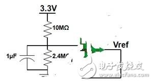
Reference voltageIn this design, the range of the ECG signal is assumed to be 0.2mV~2mV. To prevent the signal from being clamped and the dynamic range of the ADC to the maximum (0V~1.25V), the design adds 0.625V bias. As shown in Figure 2, the resistor divider and buffer generate a 0.625V reference voltage, which is also used to bias the ECG signal (see Figure 1).
If the electrode is not in good contact, the HRM should provide an alarm signal. If the input of the micropower instrumentation amplifier uses two 20MΩ resistors (see Figure 1), the input will be biased to a fixed level when the electrode is off the body. In normal operation, the output of the micropower instrumentation amplifier is the reference voltage; if one electrode falls off, the output will become 0V. Figure 3 shows the lead-off detection circuit, the output of the micropower instrumentation amplifier is connected to the detection circuit. Input.
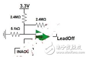
In fact, the lead-off detection circuit is a comparator with hysteresis implemented with an amplifier. When operating from a single supply, the reference voltage must be biased to allow the circuit to operate completely in the first quadrant. Figure 4 shows the implementation. The resistor dividers (R2 and R1) generate a positive reference voltage for comparison with the input voltage. The formula used to design the DC threshold is given in Figure 4.
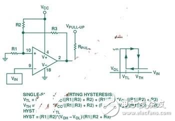
Referring to FIG. 3, R1=5.1kΩ, R2=R3=2.4MΩ, Vcc=3.3V, Vol=0V, Voh=3.3V. Using the formula in FIG. 4, Vtl=0.006983V, Vth=0.013966V,
Hysteresis = Vth - Vtl = 0.006983V.
In normal operation, the output of the micropower instrumentation amplifier should be Vref; if the lead is off, the output of the comparator will be 0V. When the output of the comparator rises to 3.3V, the output of the micropower instrumentation amplifier is also 0V. The microcontroller's interrupt mode, rising edge or high level can trigger the microcontroller's interrupt. When the lead is connected again, the output of the comparator will drop to 0V, and a falling or low level can trigger an interrupt.
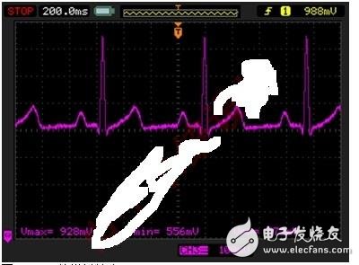
Signal processing in a micro-converterFigure 5 shows the analog output of the HRM. We can see the 50Hz noise coupled from the 220V power line. The acquired signal can be processed by a digital notch filter in the microconverter. To this end, we designed a second-order FIR filter based on a sampling frequency of 200 Hz. The notch filter is used to suppress 50 Hz interference. The selected design program is a zero pole configuration method.
Glass Plate Type Liquid Level Gauge Self-closing Valve Body
Glass plate type liquid level gauge self-closing valve body,liquid level gauge self-closing valve body,self-closing valve body,liquid level gauge self-closing valve body price
Taizhou Jiabo Instrument Technology Co., Ltd. , https://www.taizhoujbcbyq.com