High precision ultrasonic ranging system based on transducer deconvolution
Ultrasonic ranging system is widely used in liquid level measurement, position angle tracking, mobile robot positioning, etc. due to its influence from light smoke, strong anti-electromagnetic interference, intuitive distance information, low cost and convenient use. ,2]. In order to be further used in applications requiring high ranging and positioning accuracy, various high-precision ultrasonic ranging processing methods have been proposed at home and abroad [3-6]. These processing methods are more directed to the received ultrasound signals and do not take into account the effects of the ultrasound transducer on the accuracy of the ranging. Based on the research of high-precision ultrasonic ranging in "Mobile Robot Ultrasonic Navigation Sensor" [7] and 863 Project "Ultrasonic Terrain Detection System", this paper studies the influence of ultrasonic transducer on ranging accuracy. An ultrasonic ranging processing method based on transducer deconvolution.
This article refers to the address: http://
1 Influence of ultrasonic transducer on ranging accuracy
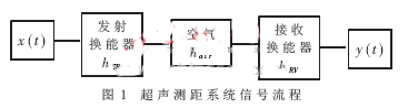
Considering the transmitting-receiving working mode of the ultrasonic ranging system, with x(t) as the transmitting signal, the ultrasonic signal obtained at the receiving end is:
![]()
Among them: hTR and hRV are the impulse response of the transmitting and receiving transducers respectively, and the hair is the impulse response of the transmitting air medium. The signal flow of the ultrasonic ranging system is shown in Figure 1.
The Cramer-Rao lower bound is the minimum error that can be achieved by the time delay estimation (TDE), and it also estimates the theoretically optimal accuracy that the system can achieve. According to the Cramer-Rao lower bound, it is assumed that the signal and noise are uncorrelated stationary stochastic processes, and the signal-to-noise ratio SNR>>1, the Cramer-Rao lower bound of the delay estimation variance is [8]:
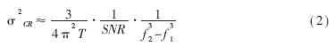
Where T is the observation window, and f1 and f2 are the upper and lower bounds of the signal bandwidth, respectively.
It can be seen from the above formula that for the delay estimation system, the wider the bandwidth of the signal, the higher the signal-to-noise ratio, and the longer the observation time, the higher the accuracy of the delay estimation that the system can achieve. Under the condition that the signal-to-noise ratio and observation time are constant, the signal bandwidth determines the accuracy of the delay estimation.
From equation (1), the bandwidth of the signal received by the ultrasonic ranging system depends on the transmitted signal, the transmitting and receiving transducer, and the air medium. For a typical ultrasonic ranging system, the ultrasonic transducer plays a major role in the signal bandwidth. Since the broadband transmission signal can be easily generated, the transfer function of the air medium is also wide-band, and the conventional air-mediated ultrasonic transducer has a narrow bandwidth for balancing the emission efficiency and the receiving sensitivity, such as the commonly used T/R40-16 ultrasound. The transducer has a center frequency of 40 kHz and a frequency of approximately 3.8 kHz at a bandwidth of 3 dB. Thus, the main influence on the accuracy of ultrasonic ranging is the narrowband frequency characteristics of the transducer.
2 Ultrasonic ranging processing method based on transducer deconvolution
In order to offset the influence of the narrowband characteristics of the transducer on the received signal, a deconvolution method can be adopted, that is, constructing a filter with an impulse response of hdecon, deconvolving the transducer impulse response and transmitting it. The combined frequency response of the accepting transducer is a broadband response, thereby outputting a broadband ultrasonic signal and improving the ranging accuracy.
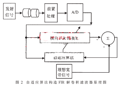
The adaptive filter automatically adjusts its impulse response characteristics by adjusting the digital coefficients of the filter with an adaptive algorithm and then determining whether the error signal is minimum according to some criteria to achieve optimal filtering. Therefore, the actual ultrasonic signal transmitted through the receiving transducer (not transmitted through the air medium) can be input to the adaptive filter, and the desired ideal wideband signal can be used as the training signal of the adaptive filter to construct the filter. After the adaptive algorithm converges, the filter needed to understand the convolution is obtained.
The schematic diagram of constructing the deconvolution filter using the adaptive filter method is shown in Fig. 2. The filter uses a lateral FIR type, LMS (Least Mean Square Error) algorithm.
3 Introduction to LMS Adaptive Algorithm
Let the input signal be X(k), the target signal be Y(k), and the filter output signal be Y'(k), then the error between the output signal and the target signal is:
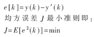
J is obviously a function of the filter impulse response h(k), so the problem of filtering is mathematically seeking h(k) which minimizes J. The LMS algorithm is a common adaptive algorithm. It is a recursive operation that does not require a priori knowledge of the statistical properties of the signal, but simply uses the instantaneous estimate to derive the optimal solution based on the recursion. The operation only obtains the estimated value of the weight coefficient of the FIR filter. With the development of time, the weight coefficient is gradually adjusted, and the estimated value is gradually improved, and finally reaches convergence. In the LMS algorithm, the weights are updated step by step:
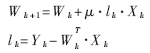
Where: Wk is the weight coefficient of the kth sampling point, ek is the error of the kth sampling point, Yk is the ideal output signal, and μ is the coefficient of control stability and convergence speed. If μ is large, the convergence will be fast, but if it is too large, the algorithm will become unstable. Generally, the value is as follows:
![]()
Where: N is the length of the FIR filter; Px is the input signal power, which is calculated as follows (M is the input to construct the impulse response sequence length of the ideal transducer):
![]()
4 Experimental results
The experimental setup is as follows: the transmitted signal x(t) is a single pulse with a pulse width of 12.5 μs; the transmit and receive transducers are T/R40-16; the ADC is MAX153, the rate is 1 Msps, 8 bits; the FIR filter weight coefficient length is 80; The output signal of the ideal filter with a bandwidth of 20 kHz through the center frequency of 40 kHz is transmitted as a training signal for constructing the deconvolution filter with the transmitted signal x(t).
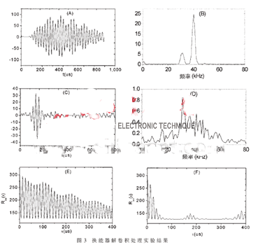
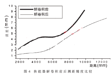
It can be seen from the experimental results of FIG. 3 that, after comparison with the received signal without deconvolution processing (time domain waveform FIG. 3A, frequency domain diagram 3B), the constructed filter is used to deconvolve the transducer characteristics. The obtained received ultrasonic signal (Fig. 3C) has a significantly wider bandwidth (Fig. 3D), and the correlation peak of the signal is sharply sharpened (Fig. 3E before processing, Fig. 3F after processing), and the maximum correlation pseudo peak attenuation is significantly improved from -0.346 dB to - 1.278dB, improved signal detection accuracy. Figure 4 shows the accuracy of the ultrasonic correlation method after deconvolution of the transducer. It can be seen that the accuracy of the system has been improved significantly, and the range accuracy within 10m is 6.6mm [9].
In order to improve the ranging accuracy of the ultrasonic ranging system, a deconvolution filter for canceling the narrowband characteristics of the transducer is constructed by an adaptive algorithm. The accuracy of the deconvolution using the transducer is more obvious than the original ranging accuracy. Improvement. This transducer deconvolution method is equally applicable to Other similar sensing systems.
Guangzhou Etmy Technology Co., Ltd. , https://www.gzdigitaltalkie.com