Design of Vehicle Vehicle Performance Testing System
Abstract: In order to ensure safe driving and reduce environmental pollution, the vehicle's handling stability, driving stability and environmental protection are tested. The detection system takes the industrial computer and the plug-in data acquisition control board as the core, and realizes the pipeline type detection of the vehicle performance by using the network and communication technology. Under normal circumstances, at least three vehicles can be simultaneously detected online, and the inspection process does not require auxiliary personnel (except for the driver), thereby reducing human error and improving detection efficiency.
Keywords: car; detection; side slip; speedometer; brake
0 INTRODUCTION During the use of the car, as the mileage increases, reliability decreases, the economy deteriorates, and the failure rate increases. This change process of the car is inevitable and conforms to the law of development, but if the test is not timely, the car will have problems during the driving process. The vehicle's overall vehicle performance mainly includes skidding, speed, braking, lighting, emissions and noise.
If you can regularly test these properties of the car, you can reduce or even avoid problems in driving.
There are two basic methods for detecting the state of the art of automobiles: one is the traditional artificial experience test method, and the other is the modern instrument and equipment test method. The artificial experience detection method has a slow detection speed and poor accuracy, and cannot be quantitatively analyzed, and is not suitable for large-scale detection. The modern instrument and equipment testing method can detect the performance of the car with special instruments and equipment when the car is not disassembled, and provide a quantitative basis for analyzing and judging the technical status of the car. The computer-controlled indoor vehicle detection system can automatically analyze, judge, store and print the technical status of the car. It is fast, economical, safe, free from external natural conditions, and has good test repeatability and quantitative display of test results. The advantages have become the main method of car inspection and have been widely used at home and abroad. The national standard stipulates the testing standards and testing methods for testing the performance of automobiles by the Taiwan test method, which makes people have evidence to rely on when designing the system.
1 Analysis of various performance testing methods
1.1 Side Slip Detection If the wheel alignment parameters are not properly matched during driving, especially if the wheel camber and the toe are not well matched, the lateral force generated by each positioning parameter will be unbalanced and lateral slippage will occur. Shift phenomenon, that is, the wheel is slippery. Using the side slip test rig to detect the amount of wheel side slip can reflect the match between the wheel camber and the toe. The sliding type sliding test rig has been widely used in China. It is based on the principle that the sliding plate can move laterally under the lateral force to measure the amount of wheel slip. According to the number of sliding plates, the sliding type sliding test bench can be divided into two types: single plate type and double plate type. The detection line adopts double plate linkage type sliding test stand.
During the side slip detection, the car slides to the side-slip test rig at a speed of 3 to 5 km/h, so that the front wheel (or rear wheel) smoothly passes through the sliding plate. During the running, the steering wheel and the steering wheel are not allowed to rotate. When passing through the platen, the amount of lateral sliding is measured. According to the provisions of GB7258-2004, the side slip test is used to detect the amount of front wheel side slip, and its value should not exceed 5m/km.
1.2 Speedometer Detection The speedometer is an important basis for the driver to drive safely. Using the drum type speedometer test bench to detect the indication error of the speedometer, the drum rotation is used to drive the wheel rotation to simulate the actual road running state of the automobile, and the actual vehicle speed is measured according to the principle that the linear speed of the drum is equal to the linear speed of the wheel, and then At this time, the indication value of the vehicle speedometer obtains the error of the speedometer. Common speedometer test stands are: standard type without drive, relying on the wheel to be tested to drive the drum to rotate; drive type with drive device, the drum is rotated by the motor. This test line uses a standard version without a drive.
GB7258-2004 stipulates that the speedometer indication error (except for the motor vehicle with the highest designed vehicle speed not greater than 40 km/h) is: the speedometer indicates the vehicle speed V1 (unit: km/h) and the actual vehicle speed V2 (unit: km/ h) should be consistent with the relationship: 0 ≤ V1 - V2 ≤ (V2/10) + 4. The wheel of the motor vehicle to be tested is driven onto the drum of the speedometer inspection table to rotate, and when the indication value (V1) of the speedometer of the motor vehicle is 40 km/h, the speed indicator of the speedometer of the speedometer indicates the indication value of the instrument ( V2) is qualified within the range of 32.8~40 km/h; when the indication value (V2) of the speedometer indicating instrument of the speedometer is 40 km/h, the indication value of the speedometer of the motor vehicle is read (V1) It is qualified when the reading of V1 is in the range of 40 to 48 km/h. When the industrial computer control system is used for the bench test, the indication value of the speedometer indicating instrument speed indicator is displayed on the computer display, and the indicating instrument is not installed on the platform.
1.3 Brake force detection The brake detection device used in the bench test method is called the brake test bench and can simulate the actual braking process approximately. When the whole vehicle is tested on the indoor drum type test bench, the drum type test bench replaces the road surface with the surface of the cylinder. During the test, the load is applied to the drum by the loading device to simulate the driving resistance, so that the car is as close as possible to the actual driving. Carry out various tests and tests under working conditions. When using the drum type brake test bench, pay attention to the following matters: the surface of the drum should be dry, there is no loose material and oil stain, and the equivalent adhesion coefficient of the drum surface should not be less than 0.75. The driver drives the motor onto the drum, the position is right, and the transmission is placed in neutral. Start the roller and measure the wheel blocking force after 2 s. Use the brake to measure the difference between the braking force of the left and right wheels and the maximum braking force of each wheel in the whole process of braking force increase, and record whether the left and right wheels are locked. When measuring the brake, in order to obtain sufficient adhesion, it is permissible to add sufficient additional mass to the vehicle or to apply a force equivalent to the additional mass (additional mass or force is not included in the axle load). When measuring the brakes, measures to prevent the movement of the motor vehicle (for example, adding a triangular block or taking traction) may be taken. After adopting the above method, the phenomenon that the wheel is locked and slipped on the drum or the whole vehicle is removed backward with the drum, and the braking force still fails to meet the qualification requirements, the other methods specified in the GB7258-2004 standard should be used instead. test.
(1) For the test of the service brake performance, the braking stability of the vehicle is detected by measuring the difference in braking force between the left and right wheels during braking. The requirements for braking force balance in GB7258-2004 are as follows: the maximum value of the braking force difference between the left and right wheels measured simultaneously in the whole process of braking force increase, and the larger of the maximum braking force of the left and right wheels of the shaft measured in the whole process. Ratio, the front axle should not be greater than 20%, and the rear axle (and other axles) should not be greater than 24% when the axle braking force is not less than 60% of the axle load; when the rear axle (and other axles) axle braking force When the load is less than 60% of the shaft load, the maximum value of the left and right wheel braking force difference measured simultaneously in the whole process of the braking force increase should not be greater than 8% of the shaft shaft load. Requirements for brake coordination time: hydraulic brakes should not be greater than 0.35 s, and pneumatic brakes should not be greater than 0.60 s. Requirements for wheel blocking force: The braking force of each wheel should not be greater than 5% of the axial load of the wheel when performing the braking force test.
(2) Parking brake performance test. When the brake tester is used to check the braking force of the parking brake of the car, the motor vehicle is unloaded, rides a driver, uses the parking brake device, and parking the brake force. The sum shall be not less than 20% of the vehicle's weight in the test state (not less than 15% for vehicles with a total mass of 1.2 times or less of the kerb mass).
(3) The complete release time of the brake, that is, the time required from the release of the brake pedal to the elimination of the brake should not exceed 0.80 s.
When the braking force is tested by the bench test method, the percentage of the axle braking force and the axle load is taken as the diagnostic standard. Therefore, the axle load must be measured before the braking force is measured. The detection line adopts the method of separating the axle load and the braking force test bench, that is, measuring the axle load on the wheel weight test bench first, and then measuring the braking force on the reaction force roller test bench.
1.4 Headlight detection Headlights are important equipment for driving road lighting for drivers at night or under low visibility conditions, and they are also light signal devices for drivers to give warnings and contact. The technical condition of the headlights can be detected by screen detection and headlamp detectors. In the safety technical inspection of motor vehicles, the headlight detector should be used to check the position of the headlight beam, and the motor vehicle to be inspected should be aligned with the headlamp detector according to the specified distance (suitable for using the vehicle aligning device). The offset values ​​of the horizontal and vertical illumination directions of the left and right far and near beams are measured on the display screen of the instrument.
The detection principle of various types of headlamp detectors is basically the same. They use a silicon photocell or a selenium photocell that can convert the absorbed light energy into a current, and the magnitude and proportion of the current generated by the photocell according to the frontlight axis. The headlight illumination intensity and the optical axis skew amount are measured. In GB7258-2004, the minimum luminous intensity of the headlight beam and the position of the beam irradiation are specified.
1.5 Emissions and smoke detection Pollutants in automotive exhaust are mainly carbon monoxide (CO), hydrocarbons (HC), nitrogen oxides (NOx), particulates and sulfides. Gases such as CO and HC in automobile exhaust have the property of absorbing infrared rays in a certain wavelength range. Moreover, there is a substantially constant relationship between the degree to which infrared rays are absorbed and the concentration of exhaust gas. The non-infrared infrared CO and HC gas analyzer is an instrument that can collect gas samples from the exhaust pipe of a car and continuously analyze the CO and HC contents.
National Standard GB/T3845-1993 "Gas Vehicle Exhaust Pollutant Measurement Idling Method", the detection of gasoline vehicle idling pollutants should be carried out under idling conditions, using a non-dispersive infrared absorption monitor, according to the specified procedures for detecting CO And the concentration value of HC. The visible pollutants discharged from the exhaust pipe of the diesel vehicle are displayed on the exhaust smoke. Exhaust smoke mainly includes black smoke, blue smoke and white smoke. The darkness of the black smoke is expressed by the exhaust smoke, and the exhaust smoke is detected by a smoke meter. The smoke meter is divided into filter paper type, light transmission type and the like. According to the national standard GB/T384-1993 ((Determination of Freedom Acceleration Smoke of Diesel Vehicles), the detection of free acceleration smoke of diesel vehicles should be measured by a filter paper smoke meter under free acceleration conditions. The procedure is carried out.
1.6 Noise Detection The noise pollution of a vehicle refers to the human's sense of hearing on a moving vehicle. The Noise Vibration Harness (NVH) is an important indicator to measure the quality of automobile manufacturing. The instrument for measuring the noise of a car specified in GB1495-2002 ((Motor Accelerated Outside Vehicle Noise Limits and Measurement Methods) is a precision sound level meter or a common sound level meter. The sound level meter is a kind of industrial noise, living noise or Traffic noise, etc., an instrument that approximates the noise level according to the auditory characteristics of the human ear. The noise level refers to the sound pressure level (dB) or loudness level (phon) measured by the sound level meter and corrected by the sense of hearing. GB7258~ In 2004, when the sound level of the motor vehicle horn is measured at 2m from the front of the vehicle and 1.2m above the ground, the value should be 90-115dB(A).
2 Detection system structure design For the detection of high-volume vehicles, using industrial computer as the control center, combined with some of the above-mentioned special testing equipment, designed the pipeline line detection system for vehicle side slip, speed, braking, lighting and other projects, the overall structure is as follows Figure 1 shows.
This article refers to the address: http://
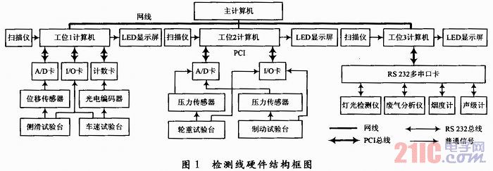
The inspection items of side slip, speedometer indication error, braking, lighting, emission, noise, etc. are divided into three divisions, the first station is responsible for the detection of the vehicle side slip and the speedometer; the second station is responsible for the axle weight of the vehicle. And the detection of braking force; the third station is responsible for the detection of automobile headlights. In addition, a main station is set up to summarize and archive the data measured by each sub-station, print the inspection report, and provide software and hardware interfaces for connection with other networks. Each station is controlled by a computer, and all inspection stations use PC-based measurement and control hardware. Through the scanner, LED large display and other auxiliary equipment, the performance of the vehicle is pipelined according to the above-mentioned station sequence. This station division can simultaneously detect at least three vehicles online, and the workload of each station is basically balanced. , thereby improving the detection speed and the degree of automation of detection.
When the pipeline is inspected, the vehicle goes online from the station, and after the second station and the third station, the inspection process is completed. It is expected that the detection time of a vehicle from the upper line to the lower line under normal conditions should not exceed 15 minutes. At each inspection station, the switch quantity signal sent by the photoelectric sensor is used to judge the entered vehicle to enter and exit the station, and the dot matrix LED Chinese character display screen is used to display the detection data, the qualified judgment result and some prompt information to the driver. The control system sends corresponding control signals according to the detection process, and automatically controls the actions of the executing device, such as lifting of the lifter, starting and stopping of the motor, and the like.
The main functions completed by the system software are: setting the measurement parameters according to the model, dynamically displaying the measurement data of the tested station, determining and displaying the measurement results, the test data is managed and counted by the database, and the test items and the pass rate statistics table are printed as needed.
3 Conclusion Compared with the traditional discrete single vehicle inspection platform, the vehicle performance detection system greatly improves the detection efficiency and the degree of automation of detection, reduces the probability of human error, and makes the detection result more scientific and credible. The system adopts industrial standards, strong anti-interference ability, fast detection speed, high accuracy, quantitative analysis of test results, suitable for large-scale detection, and has become the development direction of current automobile detection technology.
Chaff Cutter,Chaff Cutter Machine,Mini Chaff Cutter,Hand Chaff Cutter
Hunan Furui Mechanical and Electrical Equipment Manufacturing Co., Ltd. , https://www.thresher.nl