ZedBoard's interrupt principle and process details
Interrupt interrupt
Overview:
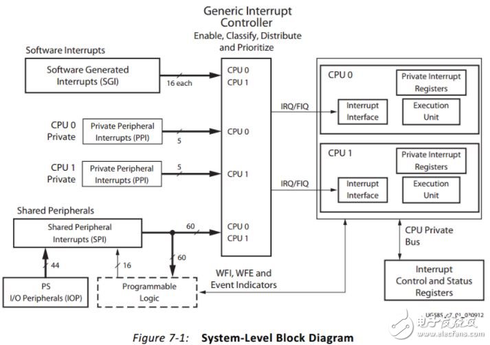
1. Zynq's interrupt types are:
Software Generated Interrupt (SGI, Interrupt No. 0-15) (16–26 reserved)
Private Peripheral Interrupt (PPI, Interrupt No. 27-31),
Shared Peripheral Interrupt (SPI, Interrupt No. 32-95).
2. Private Peripheral Interrupt (PPI): Each CPU has a set of PPIs, including global timers, private watchdog timers, private timers, and FIQ/IRQ from PL.
3. The software interrupt (SGI) is routed to one or two CPUs and generates SGI by writing to the ICDSGIR register.
4. Shared Peripheral Interrupt (SPI) is generated by various I/O controllers and memory controllers on the PS and PL. These interrupt signals are routed by the CPU.
5. The Generic Interrupt Controller (GIC) is a core resource used to centrally manage the set of resources for interrupt signals generated from PS and PL. The controller can enable, disable, mask the interrupt source, and change the priority of the interrupt source, and send the interrupt to the corresponding CPU, which accesses the registers through the private bus.
6. Interrupt Controller (ICC) and Interrupt Controller Distributor (ICD) are subsets of GIC registers.
7. (External) Interrupt Request (IRQ), Fast Interrupt Request (FIQ)
When an abnormal interrupt occurs, after the system executes the current instruction, it will jump to the corresponding abnormal interrupt processing. When the execution of the exception interrupt handler is completed, the program returns to the next instruction at which the interrupt instruction occurred and execution continues. When entering the exception interrupt handler, the execution thread of the interrupted program is saved. The execution site of the interrupted program is restored when exiting from the interrupt handler.
Interrupt Register Overview
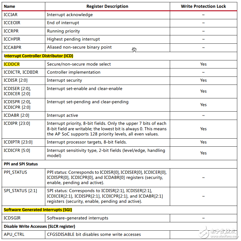
1. Interrupt Distributor (ICD Register):
1) ICDDCR: (0xF8F01000) The ICD allocates a control register that controls whether the interrupt configuration is turned on or off.
2) ICDICFR: ICD Configuration Register. Configure interrupt trigger mode (high and low), a total of 6 registers, respectively, ICDICFR 0-ICDICFR5 (0xF8F01C00-0xF8F01C14), each register 32 bits, accounting for 4 bytes, the meaning of each register is different, every 2 Bit represents an interrupt, 32 bits x6/2=96, which includes all interrupts,
3) ICDIPR: (0xF8F01400-0xF8F0145C) ICD interrupt priority register, a total of 24 registers, ICDIPR 0-ICDIPR 23, 32 bits per register, accounting for 4 bytes, each 8 bits represents an interrupt, 32 bits x 24/8 =96, including all interrupts.
4) ICDIPTR: (0xF8F01800-0xF8F0185C) ICD CPU interface selection register, configure CPU interface selection (cpu0/cpu1), including 24 registers, ICDIPTR 0- ICDIPTR 23, 32 bits per register, accounting for 4 bytes, every 8 The bit represents an interrupt, 32 bits x24/8=96, which includes all interrupts.
**5) ICDICER: Interrupt disable enable register, **3 registers, ICDICER 0- ICDICER 2 (0xF8F01180-0xF8F01888), 32 bits per register, 4 bytes, each bit represents an interrupt, 32 bits x3 =96, including all interrupts. Writing 1 means not enabling (masking).
**6) ICDISER: Interrupt enable register, **3 registers, ICDISER 0- ICDISER 2 (0xF8F01100-0xF8F01108), 32 bits per register, 4 bytes, each bit represents an interrupt, 32 bits x3= 96, including all interruptions. Writing 1 means enabling.
7) ICDICPR: Clear interrupt wait register. Three registers, ICDICPR 0- ICDICPR 2 (0xF8F01280-0xF8F01288), each register 32 bits, occupying 4 bytes, each representing an interrupt, 32 bits x3 = 96, including all interrupts. Writing a 1 indicates clearing the interrupt wait state.
Register address interrupt number
ICDICFR0 0xF8F01C00 #0-#15
ICDICFR1 0xF8F01C04 #27-#31(16-26 Reserved)
ICDICFR2 0xF8F01C08 #32-#47(36 Reserved)
ICDICFR3 0xF8F01C0C #48-#63
ICDICFR4 0xF8F01C10 #64-#79
ICDICFR5 0xF8F01C14 #80-#95(93/94/95 Reserved)
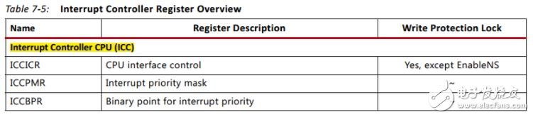
2. Interrupt controller (ICC register):
1) ICCPMR: (0xF8F00104) interrupt priority mask register, set the interrupt priority of the CPU. (Compared with ICD interrupt priority. Cpu can handle more than the priority value written to this register.) Xil_Out32(0xF8F00104, 0xF0); Set cpu interrupt priority to F0.
2) ICCICR: (0xF8F00100) ICC CPU interface configuration register, configure the CPU interface. Enable an interrupt, such as IRQ: Write_Reg (0xF8F00100, 0x07). Even if the processor can receive IRQ, enable the interrupt signal to connect to the processor.
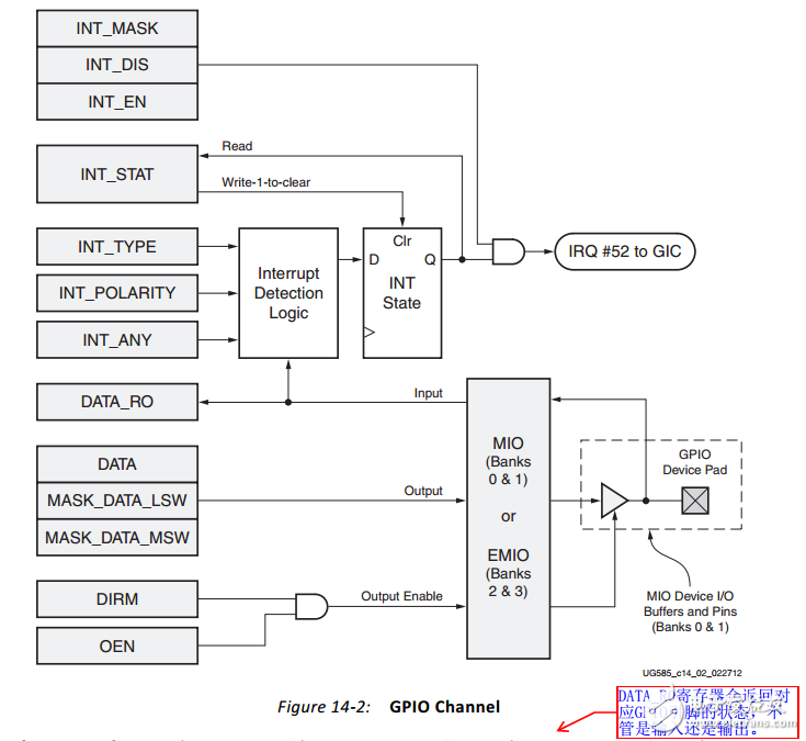
GPIO interrupt source configuration
All GPIOs share an interrupt (#52, bank1) and must check the value of INT_MASK and INT_STAT on the software to determine which GPIO has caused the interrupt.
1. INT_MASK (0xE000A20C): Interrupt mask register, read only, reading the value of this register can show which bits are masked and not masked (even if enabled).
2. INT_ENT (0xE000A210–): Interrupt enable register (4 banks, 4 registers). Write 1, the corresponding pin interrupt function is turned on, even if it can.
3. INT_DIS (0xE000A214-): Mask register (4 banks, 4 registers). Write 1, the corresponding pin interrupt mask.
4. INT_STAT (0xE000A18–): Interrupt status register (4 banks, 4 registers). Each bit represents an interrupt event on the corresponding pin. When the interrupt occurs, the interrupt flag bit of this pin is 1. If a 1 is written to this bit, the interrupt flag of this pin is cleared and 0 is written.
5. INT_TYPE (0xE000A21C–): Interrupt type register (4 banks, 4 registers). Write 1 represents the edge-triggered interrupt and write 0 represents the level-triggered interrupt.
6. INT_POLARITY(0xE000A220–): Interrupt polarity register, which controls the trigger condition of the interrupt (4 banks, 4 registers). Write 1 for high or rising edge trigger, write 0 for low or falling edge.
7. INT_ANY(0xE000A224–): Interrupt edge trigger type setting register (4 banks, 4 registers). Writing a 1 indicates that the rising edge and the falling edge are simultaneously triggered, and writing 0 indicates a single edge triggered interrupt, which is valid only when INT_TYPE is set to the edge triggered interrupt (write 1).
Customized PVC Bluetooth Charger
Shenzhen Konchang Electronic Technology Co.,Ltd , https://www.konchang.com