Electronic snoring device II
Photocoupler
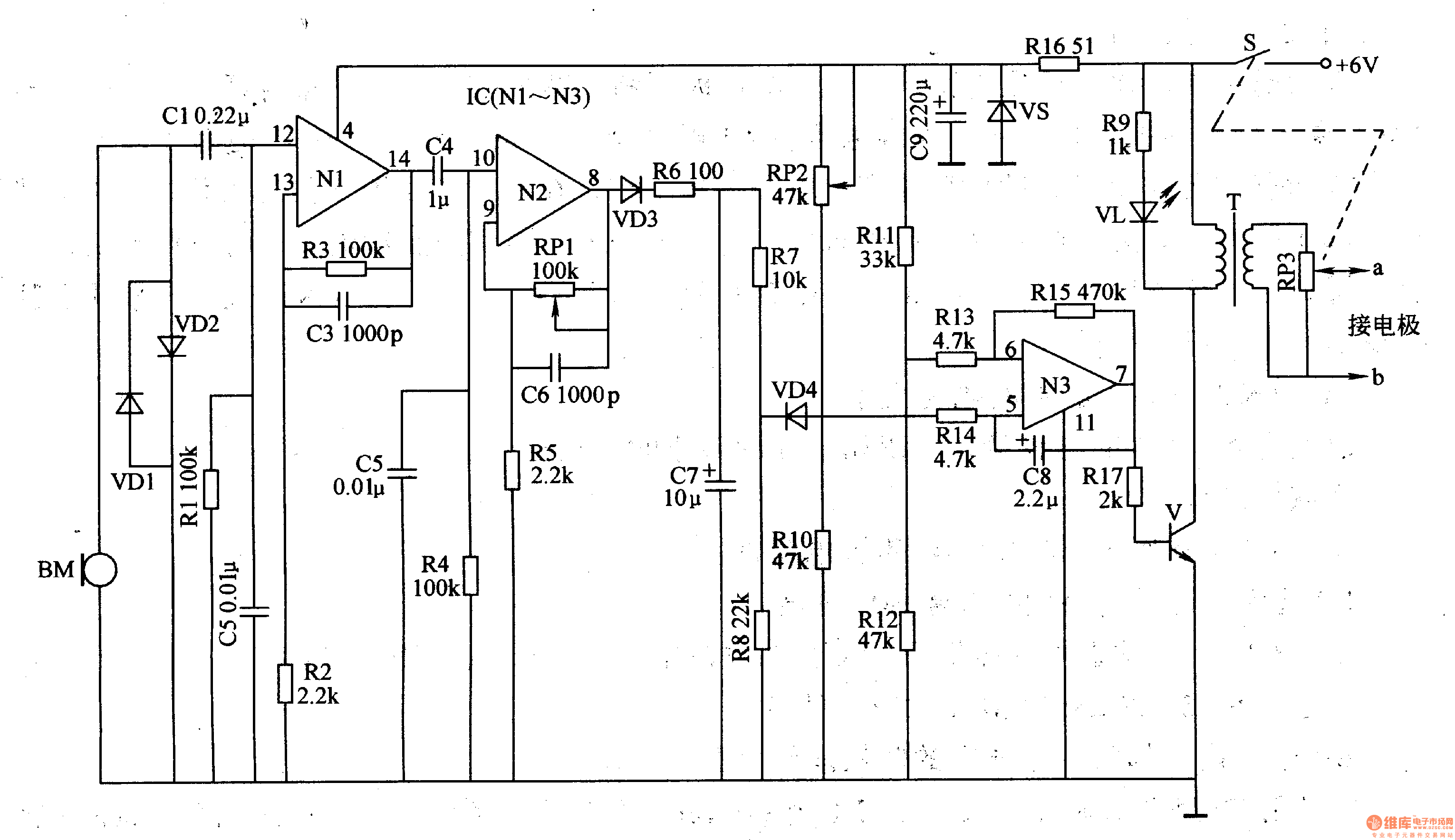
Circuit Operation The click detection circuit consists of a microphone (microphone) BM, a limiting diode VD1, a VD2, a coupling capacitor C1, and frequency selection components R1 and C2.
The preamplifier circuit is composed of operational amplifiers N1, N2 and peripheral components inside the operational amplifier integrated circuit IC (N1-N3).
The pulse generation circuit (which belongs to the low frequency self-excited oscillator) is composed of an operational amplifier N3 and a peripheral RC element inside the IC.
The pulse conversion circuit is composed of a switching tube V, a step-up transformer T, a potentiometer RM, and the like.
When the microphone BM does not detect the click sound, the output end of the operational amplifier N2 (the 8 pin of the IC) is outputted by the audio signal, and the VD4 is turned on because the negative pole is at the low level, the pulse generating circuit does not work, and no low frequency pulse signal is output. The pulse conversion circuit also has no pulse voltage output.
When the user snoring, the microphone BM converts the sound into an audio electric signal. After the signal is amplified to a certain gain by the preamplifier, the signal is output from the output of the amplifier N2, rectified by the diode VD3, and filtered by the capacitor C7 to make the VD4 The negative pole becomes high level, VD4 reverses off, the pulse generating circuit oscillates, and the low frequency pulse signal (frequency is 2 Hz) is output from the output end of the amplifier N3, and the pulse signal is boosted and transformed by the pulse conversion circuit, at a, b A pulse voltage is generated at both ends.
Adjusting the resistance of RPl can change the amplification gain of N2, thus changing the sensitivity of potassium sound detection.
Adjusting the resistance of RO2 can change the sensitivity of VD4 action.
Adjusting the resistance of RP3 can change the magnitude of the electrical pulse amplitude.
By changing the capacitance of the capacitor C8, the operating frequency of the pulse generating circuit can be changed.
Component selection
Rl-Rl5 and Rl7 use 1/4W or 1/8W carbon film resistors; R16 uses lW metal film resistors.
RPl and RP2 use small potentiometer or sealed variable resistor; RP3 selects small synthetic carbon film potentiometer with switch.
Cl, C2, C4 and C5 use monolithic capacitors or polyester capacitors; C3 and C6 select high-frequency ceramic capacitors; C7-C9 selects aluminum electrolytic capacitors with a withstand voltage of 16V.
VDl-VD4 selects 1N4148 type silicon switch diode for use.
VS selects 5.lV, l/2W silicon steady voltage diode.
VL selects red LED of φ3mm for use.
V selects FNO2C or MJEl3005, KD55 type Darlington transistor.
The IC uses the LM324 type integrated operational amplifier circuit.
T selects 3-5W, 6V power transformer, when it is used, it connects its primary winding to RW, and its secondary winding is connected to +6V power supply and V collector.
The BM uses an electret microphone (microphone) or a φ27 mm piezoelectric ceramic piece with a sound assisting cavity.
UV Screen Protector,UV Curing Machine,UV Curing Screen Protector
Shenzhen Jianjiantong Technology Co., Ltd. , https://www.mct-sz.com