Principle and application knowledge sharing of three-level inverter
Comparative Analysis of "I" and "T" Type Circuits of IGBT Module Three-Level Inverter
With the continuous development of solar energy and UPS technology and the continuous expansion of the market, the requirements for inverter efficiency are increasingly being valued by manufacturers, so the three-level topology has emerged. It is well known that, compared with the conventional two-level structure, the three-level structure has the advantages of small harmonics, low loss, high efficiency, and the like in addition to halving the blocking voltage of a single IGBT . This paper mainly analyzes the waveforms of "I" and "T" type circuits based on the existing three-level research, and selects the specifications of the switch tube based on the waveform analysis, loss, etc. The aspects were analyzed and compared, and finally a suitable three-level circuit was selected. Article source: http://
First, three level circuit schematic
At present, there are many kinds of three-level topologies for IGBT modules . The two most common topologies are three-level "I" type and three-level "T" type. Next, the two structures will be analyzed from different aspects. . As shown in Figures 2 and 2, in order to distinguish the two circuits, according to the arrangement of the four IGBT switch tubes in the circuit diagram, we will become the I-type, the latter called T. Font type. Compared with the ordinary half-bridge circuit, the three-level circuit has a good effect of improving the output ripple and reducing the loss because of the ability of the mid-point freewheeling.
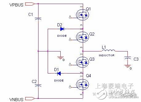
Figure 1. Schematic diagram of a three-level "1" shaped circuit
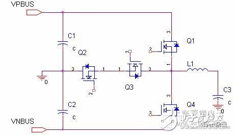
Figure 2. Schematic diagram of a three-level "T" shaped circuit
Second, the waveform analysis of the two circuits
In order to compare the loss and specifications of the two circuits, the waveforms of the two circuits are depicted in this paper, as shown in Figure 3 and Figure 4.
The following is a partial description of the waveform.
1. The waveform diagram assumes that the positive and negative bus are equal, and each component is assumed to be an ideal component.
2. The way to drive the signal
For the two circuits, the same drive signal waveform is selected for analysis. The specific control method of the drive signal comes from the reference [1][2], as shown in the figure, where Q1, Q3 are a group of PWM (with dead zone). Time), Q2, Q4 A set of PWM (with dead time), and Q1, Q4 also contains dead time.
3. The waveform diagram assumes that the inductor current iL is the same and covers several conditions of all current states (see below for identification).
4. VL indicates the voltage at which the inductor is connected to the switch tube. It can be seen from the waveform diagram that the voltage waveforms of the two circuits are the same.
5. The high level of VL is 1 times Vbus, and the other level values ​​are based on the height ratio.

Figure 3, 1 word type three-level circuit waveform analysis and principle small video

Figure 4, T-type three-level circuit waveform

Three-level inverter output waveform
Third, the comparison of the two circuits
1. Comparison of switch tube withstand voltage specifications: In the three-level I-type circuit, four IGBT tubes are subjected to the same voltage, while the T-type Q1 & Q4 tubes are subjected to twice the voltage. For example, if the DC bus is 600V, the I-type 4 IGBT tube blocking voltage is 600V/650V, and the T-type Q1&Q4 tube is 1200V.1200V IGBT chip has greater switching loss and conduction loss than the 600V/650V chip. This means that the chip has more heat and requires more silicon chips. With the increase of silicon chips, the cost will inevitably increase. However, in practice, for the I-type circuit, when the voltages of the two switching tubes are subjected to 2 times the BUS voltage in series, the voltages of the two switching tubes cannot be exactly the same due to the difference of the components themselves, therefore, in order to ensure the switching tubes For safe operation, the switch tube in the I-type circuit should also be designed to withstand 2 times the BUS voltage. Therefore, from a practical point of view, the 1-word circuit does not have much advantage in the selection of the withstand voltage of the switch.
2 , the comparison of loss
The losses here mainly refer to the four switching tubes, and the diode switches and conduction losses.
Because the loss is closely related to the flow path of the current, it is divided into six states according to the flow path of the current. According to different colors, it is shown in Figures 3 and 4, please refer to it.
i. positive bus power supply status,
In the A- type circuit, the current is supplied by +BUS and Q1 and Q2.
Its losses include Loss_Q1_turnon&turnoffLoss_Q1_On Loss_Q2_On
In the B- type circuit, the current is supplied by +BUS via Q1.
Its loss includes Loss_Q1_turnon&turnoffLoss_Q1_On
Comparison: In this state, it can be seen that the Loss_Q1_turnon&turnoff is similar in the waveform diagram, but the 1-word circuit has one more conduction loss than the T-type circuit.
Ii. Negative bus power supply status
In the A- type circuit, the current direction is from the inductor, through Q3, Q4 to negative bus.
Its losses include Loss_Q4_turnon&turnoffLoss_Q3_On Loss_Q4_On
B, T- type circuit, the current direction is from the inductor, through Q4 to negative bus
Its loss includes Loss_Q4_turnon&turnoffLoss_Q4_On
Comparison: In this state, the 1-word circuit has one more conduction loss of Q3 than the T-type circuit.
Iii. Positive BUS freewheeling status
In the A- type circuit, the current direction is from the inductor through Q1diode, Q2diode to positive bus.
Its losses include Loss_Q1diode_turnon&turnoff&on
Loss_Q2diode__turnon&turnoff&on
In the B- type circuit, the current direction is from the inductor through Q1diode to positive bus.
Its losses include Loss_Q1diode_turnon&turnoff&on
Comparison: In this state, the 1-word circuit has one more conduction loss of Q2 than the T-type circuit.
Iv. Negative bus freewheeling state
In the A- type circuit, the current direction is from negative bus via Q1diode, Q2diode to inductor.
Its loss includes Loss_Q3diode_turnon&turnoff&on
Loss_Q4diode__turnon&turnoff&on
In the B- type circuit, the current direction is from negative bus through Q1diode to the inductor.
Its loss includes Loss_Q4diode_turnon&turnoff&on
Comparison: In this state, a word-type circuit has one more conduction loss of Q3 than a T-type circuit.
v. Midpoint freewheeling iL>0 state
In the A , 1-word circuit, the current is from GND, through D1, Q2 to the inductor.
Its loss includes Loss_D1 Loss_Q2
In the B- type circuit, the current is from GND, through Q2, Q3diode to the inductor.
Its loss includes Loss_Q2 Loss_Q3diode
Comparison: In this state, the two circuit losses are close.
Vi. midpoint freewheeling iL<0 state
In the A , 1-word circuit, the current is passed through the inductor, via Q3, D2 to GND.
Its loss includes Loss_Q3 Loss_D2
In the B- type circuit, the current is supplied by the inductor through Q3 and Q2diode to GND.
Its loss includes Loss_Q2 Loss_Q3diode
Comparison: In this state, the two circuit losses are close.
Conclusion: It can be seen from the above comparison that in addition to the mid-point freewheeling state, the loss of the T-type circuit in other states is better than that of the 1-word circuit.
3 , the comparison of the number of components
From the topology diagram, it is easy to see that the T-type circuit has two more Diodes than the 1-type circuit, which is good for reducing the space. 4. Different control timing
The three-level I type needs to first turn off the outer tube Q1/Q4, then turn off the inner tube Q2/Q3 to prevent the bus voltage from being applied to the outer tube and cause damage; while the T-type has no timing requirements. In addition, for the I-type topology, four independent power supplies are required for the drive design; for the T-type common emitter topology, only three independent power supplies are required. Type I and T-type losses are different. When the power factor is close to 1, the switching frequency is increased (>16KHz), the three-level I-type (600V) is lower in loss and higher in efficiency; and when the switching frequency is reduced (<16KHz) ), the three-level T-type (1200V) has lower loss and higher efficiency. Therefore, when designing an inverter system, a high-efficiency topology should be selected according to different switching frequencies. 5. The commutation path is different. In the T-type topology, the conversion paths between the outer tube and the inner tube are the same. In the I-type topology, the commutation path is different, which is divided into a short commutation path and a long commutation. Path, so when using a discrete module for a three-level I-type topology, you must pay attention to the problem of stray inductance and voltage spikes.
Fourth, the conclusion:
It can be seen from the analysis of this paper that the T-type and 1-word three-level circuits are theoretically superior to the T-type circuit in terms of withstand voltage. However, from the perspective of practical application, the difference between the two is small; In terms of loss, the T-shape is better than the 1-word type; in terms of the number of components, the T-shape is less than two Diodes.
Therefore, according to the analysis in this paper, the T-shaped circuit will be advantageous in terms of smaller loss and space reduction.
Function description
The socket is ordinary converter,with two output 5V2A power USB power supply at the same time,can be very convenient in use electrical appliances and recharge the equipment at the same time,such as digital products like Iphone Ipad,MP3,MP4 etc.The charge apply to full range of international AC output,no-load power consumption less than 0.3W,with short circuit,overload,over-voltage protection,can be convenient for your life and save more energy
Timer Control Time Adgustment
1.Press the power switch 1 time,the 1HOUR LED will light on.The Timer into ON mode,USB and control socket output ON .
2.Continuously press the power switch the LED light on,the Countdown mode and LED light on will cycle change from 1HR,2HR,4HR,6HR,8HR,10HR.
3.Choose you need countdown time mode,the mode LED will lighto on,start countdown until countdown time finish,the control output and USB change to OFF
4.Then the countdown is start,The Time indicate LED will from high to low auto change until Countdown finish off.
Failure analysis:
1.check whether the power supply connection is good
2.check whether the USB cable is loosen
Warning Note:
1.Use indoor and dry location ONLY
2.The load max does not exceed 15A 3600W
3.This product does not convert voltage please do not miss use DO NOT exceed the maximum loading of 3600 Watts 15A
4.Always have earth connection for safety reason
5.If in doubt please consult with a qualified electrician
USB countdown timer, USB countdown timer socket, USB timer, USB charger timer, USB timer socket
NINGBO COWELL ELECTRONICS & TECHNOLOGY CO., LTD , https://www.cowellsocket.com