AC servo integrated driver design analysis
The AC servo drive control includes the drive control of the AC asynchronous motor and the permanent magnet synchronous motor. Traditional AC servo drive control requires the establishment of a customized servo control system. While software design platforms that provide custom computing can alleviate the mental effort of coding design, today's applications have almost reached the limits of software-based solutions. Therefore, there is a need for a new method that simplifies design and provides higher performance.
Integrated design platform
The traditional motor drive controller design is not only prone to some "soft" errors, but also difficult to meet the development time requirements of the fast multilateral market. For motor drive controller designers, a motion control design platform that includes configurable digital and analog control techniques, as well as power circuit and power switching device driver circuit solutions, greatly simplifies design. International Rectifier (IR)'s IRMCS201 design platform, which integrates hardware and software, has become a model for AC servo-driven motion controller design platforms. The design platform includes a servo drive controller and a ServerDesigner software tool. The core of the servo drive controller is the motor control chip IRMCK201. The IRMCK201 chip, designed around the International Rectifier's MoTIon Control Engine (MCE), is part of the iMoTIon IP family. The MCE in the iMoTIon chipset can perform Field Oriented Control (FOC) control in 6μs, while the high-performance programmable DSP requires 15~20μs, which is 20 times faster than the traditional DSP. MCE is faster because it is set up as a parallel hardware controller signal processor, avoiding the difficulties encountered with traditional microcontrollers or DSP architectures, enabling analog control bandwidth while providing more flexibility. With enhanced digital control performance. As a result, the MCE can support higher torque control bandwidths for more control and peripheral functions without exceeding the effective cycle time. In addition, the IRMCK201 is closely matched with the appropriate analog and power electronics components selected from the iMoTIon database to provide users with a reference to the servo drive controller hardware design.
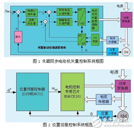
The software tool ServerDesigner developed for the application of the dedicated chip for motor control is installed on a PC. Customers only need to use ServerDesigner software to configure the memory on the chip through the communication port on the chip, and then adjust the control according to specific needs to meet the required design specifications. The main communication logic includes an asynchronous communication interface for RS232C, RS422 or RS485 communication, as well as a fast SPI interface and an 8-bit wide Host Parallel Interface. All communication ports have the same access to the memory, allowing the user to read and write each of the selected memory locations and configure and detect the drive with any available port. This simplifies the original complex design process. The servo drive control calculation architecture set by the iMotion IP core module is shown in Figure 1. It can be seen from Figure 1 that IR's motor control chip only includes speed regulation control and current control. To achieve position servo control, a position controller is also required, as shown in Figure 2. This is because the position control is flexible and difficult to be versatile.
Servo controller design
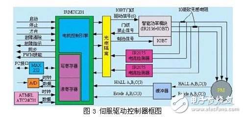
According to the hardware design reference of the servo drive controller provided by the IRMCS201 design platform, the servo drive controller shown in Figure 3 can be designed.
Host interface
The IRMCK201 chip provides RS232/RS422/485, SPI interface or 8-bit parallel interface to communicate with external host. RS232/RS422/485 communication mode can be programmed. Through the MAX232 level conversion chip, the RS232 interface allows the PC host to directly configure the contents of the MCK201 register and monitor the operating status of the system. Different communication methods are usually active and can be switched to each other, but not at the same time.
Motor control interface
The IRMCK201 chip has six SVPWM outputs, and the power switching device IGBT of the three-phase bridge inverter is driven by the optocoupler and the IR2136 chip, and can also be directly interfaced with the intelligent power module. The driver chip IR2136 has the function of preventing the same bridge arm through logic and undervoltage and overcurrent to close all outputs. The IRMCK201 provides a direct interface to the IR2175 linear current sensing chip. The IR2175 has a maximum input voltage of 260mV and has the ability to convert an analog input signal to a 130kHz PWM signal.
IRMCK201 has an encoder interface circuit. The number of encoder pulses is from 200 to 10,000 revolutions, and the pulse frequency can be as high as 1 MHz. It can easily form a speed servo control system. It can be connected to a variety of encoders, and can receive ENA, ENB and zero mark signals that are mutually orthogonal, and three HALL signals are input. These three signals can be used independently or multiplexed. When the system is powered on, the IRMCK201 can estimate the initial position of the rotor pole of the permanent magnet synchronous motor through the HALL sensor signal and the Z pulse position.
Control input and status indication interface
The IRMCK201 has digital IO pins such as control inputs and status indicators. The control input signal includes start, stop, running direction, fault clearing, etc.; the status indication signal includes a system fault indication, a PWM output enable, a synchronization indication, and the like.
Serial memory interface
IRMCK201 has a serial memory interface. After power-on reset, the chip reads the data configured in the memory through the I2C bus without host intervention. Therefore, the system can be run alone without host control, and its initialization data is obtained by reading the contents of the serial memory.
Controller parameter configuration
The motor parameters and control parameters are downloaded to the registers in the MCK201 using the ServerDesigner software tool installed on the PC to complete the configuration of the control system without software programming. Motor parameters include rated speed, winding resistance, inductance, rated current, motor inertia, pole number, no-load current value, encoder accuracy and type. For permanent magnet synchronous electric, there are voltage constants and torque constants. Control parameters include PI regulator parameters, acceleration and deceleration time, and PWM carrier frequency and dead time.
Conclusion
For advanced motor controllers, as application range and speed requirements continue to grow, developers need to quickly deploy solutions to meet increasing performance requirements. A motion control design platform that includes optimized analog control, power switching and drive technology, and digital control based on high-performance hardware solves both development time and performance requirements. With the advent of single-chip digital controllers that can be easily configured, this controller can reduce the risk of design for those who lack professional software or power system design capabilities.
Ac Contactor,Contactor For Ac Unit,Compressor Contactor,Air Conditioner Contactor
NanJing QUANNING electric Co.,Ltd , https://www.quanningtrading.com