Design of Intelligent Remote Control Campus Wireless Broadcasting System
1 New intelligent remote control campus wireless broadcasting system introduction
The intelligent remote control campus wireless broadcasting system is a brand-new campus wireless broadcasting system integrating wireless communication, sound and digital technology. The campus wireless broadcasting system adopts the dual tone multi-frequency DTMF (Dual Tone MulTI-Frequency) communication method of telephone dialing. Dual-tone multi-frequency is a reliable and mature communication technology. Because it provides a higher dial rate, it quickly replaces the dial pulse signaling used by traditional rotary telephones. In recent years, DTMF has also been used in interactive control systems, such as language menus, language mail, telephone banking, and ATM terminals. DTMF has low requirements on the transmission circuit, and can receive and send signals through ordinary telephone lines, with a long transmission distance, and there are a variety of models of universal dual audio components for selection. The transmitter of campus wireless broadcasting system adopts stereo wireless frequency modulation. In order to avoid that the addressing control signal interferes with the broadcast audio signal, the left channel is the broadcast audio signal, and the right channel is the dual audio signal used for receiver addressing. The modulated radio frequency signal is transmitted to the receiver of each broadcasting point through the electromagnetic wave transmitted into the space. After receiving the radio frequency signal through the antenna, the receiver detects the audio signals of two channels in stereo. The left channel broadcast audio signal is sent to the power amplifier for amplification; the right channel dual audio control signal is sent to the dual audio decoding circuit for decoding to obtain the corresponding binary control code. The control code is sent to the single chip microcomputer in the receiver. The single chip microcomputer turns on or off the power of the power amplifier part of the receiver according to the machine code set in the machine, so as to realize the function of fixed point / zone control of each relevant broadcast point FM receiver. The block diagram of the intelligent remote control wireless broadcasting system is shown in Figure 1. The left side of Figure 1 is the manual button, remote communication terminal, and PC, which are mainly used to realize the control function of the wireless broadcasting system. In addition to the control function, the PC can also provide broadcast source signals to the system.

2 The hardware design of campus broadcasting system control
The intelligent remote control campus wireless broadcasting system mainly includes four parts: FM transmitter, FM receiver, control system and broadcast audio source. This article focuses on the control system of wireless broadcasting. The control system can be divided into manual button control, PC host computer control, and remote telephone remote control. The key component of the entire control system is the digital addressing encoder. Various control methods will eventually control the entire wireless broadcasting system through the addressing encoder.
2.1 Digital encoder
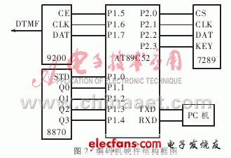
The core components of the digital encoder are the single-chip AT89C52 and the DTMF transmitter 9200. Manual key control, telephone remote control and PC host computer control will eventually send control information through the 9200 with the help of the microcontroller in the encoder. The biggest difference between the different control methods is that the control commands for the entire wireless broadcasting system are sent to the single-chip microcomputer through manual keys, remote communication terminals and PCs. The hardware structure of the encoder is shown in Figure 2.
In Figure 2, 8870 is a DTMF receiving chip, which is used to receive DTMF signals from remote phones. 7289 is a serial interface chip that integrates input keyboard and output display, and is connected with manual operation buttons. After the control codes obtained according to different control methods are sent to the single-chip microcomputer, the single-chip microcomputer sends the control codes to the DTMF sending chip 9200 through a serial interface. The 9200 generates corresponding dual audio signals according to different codes, and then passes the dual audio signals through The transmitter is modulated and transmitted into the air, and reaches each receiver through the propagation of electromagnetic waves.

2.2 Manual control part
The core component of the manual control part of the circuit is: an integrated chip ZLG7289A that integrates keyboard input and output display. ZLG7289A has a serial interface function, which can simultaneously drive 8-bit common cathode digital tubes. Each digital display tube can independently control attributes such as blanking and blinking, and provides instructions for circular left / circular right shift display. The ZLG7289A can also be connected to a keyboard matrix with up to 64 keys, and the keyboard controller contains a debounce circuit.
When the keys are manually operated, if a key is pressed, the key value is sent to the 7289 chip, and then the key value is sent to the microcontroller in the encoder. After the key value is processed by the microcontroller, it is sent to the encoder as a control code. Of 9200. In this way, the addressing control of fixed point or partition can be finally realized by operating the keys. In the wireless broadcasting system, when there are many broadcasting points, multiple 7289 can be set in the manual key panel, each 7289 has its own chip selection signal, so that the single chip can choose the device.
2.3 PC control part
The realization of the control of the entire wireless broadcasting system by the PC depends on the special broadcast control software. Its main functions have two aspects: the management of the sound source information and the addressing control. In terms of audio source information, you can use the shared resources of the computer and the network to add various audio source information to greatly enrich the content of wireless broadcasting. At the same time, it is also very convenient for the management of audio source programs. Various playback management can be carried out through the broadcast control software: timing playback, loop playback, selection of audio source programs, etc .; addressing control, when fixed-point or partition playback is required, the PC machine enters the encoder The MCU sends the corresponding code, through the flexible interface function of the MCU, according to the different control requirements of the code, send the corresponding control code to the 9200, and then achieve the purpose of controlling the various wireless broadcast receivers. The serial communication is adopted between the PC and the single-chip computer. The PC is the upper computer and the single-chip computer is the lower computer.
2.4 Telephone remote control
Telephone remote control can realize remote control of the entire wireless broadcasting system. The remote control system uses program-controlled exchange signals (DTMF dual-tone multi-frequency signal, ringing signal, etc.) as system control commands, so that users can send DTMF dual-tone multi-frequency signals at the far end using fixed phones or mobile phones to achieve near-end wireless Remote control of broadcasting system equipment.
After the encoder receives the DTMF signal from the remote phone, it is decoded by a dedicated DTMF receiver chip, and the decoded signal is processed by the single-chip microcomputer. Perform the corresponding operation according to the dial-up transmitted from the remote communication device. The password must be checked first. If the password is correct, the corresponding operation can be performed according to the information sent from the remote communication device (such as the operation of the receiver of the fixed-point or group on / off wireless broadcast system), and finally the campus wireless Remote control of broadcasting system.
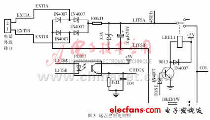
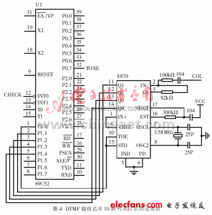
The remote control circuit is mainly divided into on-line circuit, drive circuit, DTMF decoding circuit, and central control unit. Both the on-line circuit and the drive circuit are constructed with discrete components, which can further control product costs. When the signal decoding circuit is connected to the user's telephone line, the system is said to be online; on the contrary, when the DTMF signal decoding circuit and voice prompt circuit are disconnected from the user's telephone line, the system is called offline. Only when the telephone remote control system works, the system should be online. This can prevent the high-voltage ringing signal and other high-voltage noise on the line from harming the DTMF signal decoding circuit and voice prompt circuit when the user calls the system. The driving circuit is realized by a relay. When the central processing unit confirms that the operation password is correct, it sends out a control signal to energize the relay, which in turn allows the DTMF signal sent from the remote personal communication device to be sent to the DTMF receiving chip. The DTMF receiver and decoder uses the CM8870, which is used to receive and decode DTMF signals, and send the decoded signals to the microcontroller in the encoder. The remote control circuit part is shown in Figure 3.

Remote control is completed by hardware and software. As can be seen from Figure 3, when the remote personal communication device dials the campus wireless broadcasting system number, the ringing signal EXTI is generated. After the ringing signal is rectified and filtered, the photoelectric coupling transistor is triggered, the tube is turned on, and the effective CHECK signal is sent to the single chip. After the MCU receives the CHECK, it sends a TONE signal, starts the drive circuit, energizes the relay, closes the contact, sends the external DTMF signal to the DTMF receiving chip CM8870, as shown in Figure 4, and thereafter the CM8870 starts to receive the DTMF signal and translate The code is sent to the single chip microcomputer, and the single chip microcomputer judges according to the preset operation password. If the password is correct, continue to send a valid TONE signal to stay online. The CM8870 continues to receive and decode to the MCU, and the MCU continues to receive codes and perform corresponding operations according to the agreement. For example, according to different codes, fixed-point or group-controlled receivers of wireless broadcasting systems. If the password check fails, the single chip microcomputer invalidates TONE, and accordingly the relay is de-energized, its normally open contact is disconnected, the external DTMF cannot be sent to the CM8870, and the system is offline.

household Beer Brewing Urn fermentation tanks brewery equipment beer alcohol processing machine for home brewery
Beer Brewing Urn
Beer Brewing Urn,Home Fermenter Beer Brewing Machine,Household Beer Brewery Equipment
FOSHAN FORTUNE ELECTRICAL APPLIANCE CO.,LTD , https://www.coffelady.com