Using asynchronous communication chip 16C552 to realize serial communication between PC and DSP
When the serial communication between the PC and the DSP is realized, the serial communication interface (SCI) module of the DSP and the SCI multiprocessor communication protocol (that is, idle line mode and address bit mode) can usually be used directly on the same serial line To achieve communication between multiple processors, serial communication can also be implemented using the SCI asynchronous communication mode. Although these two methods can easily achieve serial communication, they both require more hardware and software resources in the system.  Therefore, it is not suitable for applications with high real-time requirements and tight system resources. In the development of the active power filter experimental system, the author successfully solved this problem because of the use of the asynchronous communication chip 16C552. This article will introduce the realization method of the program from two aspects of circuit structure and software programming.
1 Introduction to 16C552
1.1 Functional characteristics and structural block diagram
16C552 is an asynchronous communication chip produced by companies such as TI (TL16C552) and VLSI (VL16C552). It has two enhanced universal asynchronous communication unit channels and an enhanced bidirectional printer port; it supports two modes of TL16C450 and FIFO, with 16 bytes of FIFO can reduce CPU interrupts; each channel has independent sending, receiving, line status and setting interrupt functions, and has independent MO-DEM control signals, programmable serial data transmission format (including data bit length, verification Mode, stop bit length) and programmable baud rate generator; in addition, the data and control bus of each channel also has a three-state TTL drive function.
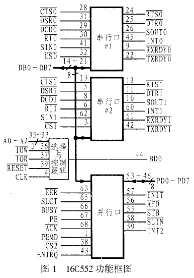
TL16C552 is a 68-pin PLC (Plastic Lead Chip Carrier) packaged chip from TI. Its pins and functional block diagram are shown in Figure 1. It can be seen from the figure that its serial port mainly completes two functions, one is to convert the serial data received by the peripheral device or modem into parallel data; the other is to convert the parallel data of the CPU into serial data for transmission . During normal operation, the CPU can read the status information of 16C552 at any time to report the type and status of 16C552 transmission operations, including various error states, such as parity, overflow, framing errors, and FIFO errors. In addition, 16C552 also has a complete MODEM control function, and has signal terminals such as CTS, RTS, DSR, DTR, RI, DCD and so on.
16C552 has a complete set of interrupt system, which can automatically set the priority. Its serial port and parallel port can work independently in interrupt and query two working modes.
1.2 Internal registers of 16C552
There are 12 single-byte registers inside 16C552. These registers occupy 8 I / O port addresses, whose addresses are determined by A0 ~ A2. Some of the registers share an I / O port address, and the shared I / O port can be distinguished by reading / writing signals and the D7 bit (DLAB) of the line control register (LCR). The specific description is listed in Table 1 and needs to be explained What is: Only when the CS0 or CS1 of 16C552 is low level, the serial channel can be accessed.
Table 1 Internal registers of I6C552
| DLAB | A2 | A1 | A0 | Symbol | Register |
| L | L | L | L | RBR | Receive buffer register |
| L | L | L | H | THR | Transmit holding register |
| L | L | L | L | IER | Interrupt enable register |
| X | L | H | H | IIR | Interrupt recognition register |
| X | L | H | L | FCR | FIFO control register |
| X | L | H | H | LCR | Line control register |
| X | H | L | L | MCR | MODE control register |
| X | H | L | H | LSR | Line status register |
| X | H | H | L | MSR | MODEM status register |
| X | H | H | H | SCR | Cache register |
| H | L | L | L | DLL | Divisor latch low |
| H | L | L | H | DLM | Divisor latch high |
The specific regulations on the content of each register are limited to space. I will not elaborate here. Those who are interested can refer to the relevant product information of TI. However, in serial communication applications, it is important to clarify several registers such as FCR, LCR, IER, etc. Content. In addition, in practical applications, sometimes D4 in the MODEM control register may be ignored. This bit is the self-test loopback status control bit. It can be used to control the self-test of the serial port. Therefore, after the self-test is completed, This bit should also be reset to ensure the normal operation of the system.
2 Communication system hardware interface circuit
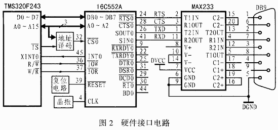
The hardware interface circuit of this system is shown in Figure 2. Among them, the address decoding circuit can be implemented by different circuits according to actual needs. In order to make the system flexible and convenient, a CPLD is used in this scheme to allocate the system address. The reset circuit can use a dedicated reset chip or a pull-up resistor. The external crystal oscillator can be selected by itself, and then the high and low bits of the divisor latch are set according to the crystal oscillator frequency, so as to obtain the correct baud rate of the communication system. The crystal oscillator used in this system is 8MHz. In addition, since 16C552A has two serial channels and a standard parallel port, the coordination between them should be paid attention to in hardware and software. It is recommended to connect the chip select of the unused port to a high level (the chip select of 16C552A is active low) to avoid errors. 
3 Serial communication software design
3.1 Communication protocol
The communication protocol of this design includes the following:
(1) The baud rate is 9600.
(2) The communication command consists of 2 bytes: the first byte is the synchronization byte 0XFF; the second byte is the command code, which is mainly used to indicate various control commands.
(3) Each byte includes 8 data bits and 1 stop bit, no check.
(4) During the communication process, the host computer sends a synchronization command to the TMS320F243, and the TMS320F243 immediately answers after receiving it, and retransmits if the answer is wrong.
(5) When the communication program sends a control command to the TMS320F243, the TMS320F243 returns to receive the correct response signal; when the communication program queries the TMS320F243 for the system parameter command, the TMS320F243 returns the required data in the prescribed format.
Both the PC and the TMS320F243 use asynchronous communication. The PC uses the event-driven method to receive data. The TMS320F243 uses the interrupt method to receive data and the query method to send data. 
3.2 Communication software design of upper and lower computer
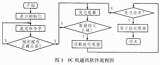
There are at least three methods for writing serial communication programs on the PC, which are assembly language, C language and Visual series communication control (MSComm). In comparison, the Visual Series communication controls can easily and efficiently complete programming tasks with a small amount of code. In actual application, the serial communication program of the PC can be written based on the communication control MSComm in Visual Basis 6.0, and the lower computer (F243) software can be written in assembly language. The serial port program flow of the upper and lower computers are shown in Figure 3 and Figure 4, respectively. The initialization procedure of 16C552 is as follows:
; THE 16C552 INITIALALZATION PROGRAM
C552_INIT:
LDP # 00h
SPKL # 83h, GSR0
OUT GSR0,0E003h; set LCR
SPKL # 34h, GSR0
OUT GSR0, 0E00h; set DLL
SPLK # 00h, GSR0
OUT GSR0,0E001h?; Set DLM
SPKL # 03h, GSR0
OUT GSR0,0E003h?; Set LCR
SPKL # 08h, GSR0
OUT GSR0,0E004h?; Set MCR
SPKL # 01h, GSR0
OUT GSR0,0E002h?; Set FCR
SPKL # 01h, GSR0
OUT GSR0,0E001h?; Set IER
RET
Figure 4
4 Conclusion
In this paper, the serial communication method between PC and DSP using asynchronous communication chip 16C552 is studied. The author has developed its serial communication software and debugged it in the experiment. The software is not only flexible and convenient to use, but also can use 16C552's FIFO mode to realize the sending and receiving of large amounts of data, thereby reducing the interruption of DSP and alleviating the shortage of system resources.
Qunsuo is a professional manufacturer of Barcode Scanner. We provide 1D Barcode Scanner and Qr Code Scanner , help customers from various industries. All of our barcode scanner support connecting with Android IOS via bluetooth. Furthermore, Our barcode scanner also support connecting with PC via 2.4G wireless module. Qunsuo provide portable scanner, Finger Barcode Scanner and Handheld Barcode Scanner. And our QS-S03 is equipped with Zebra scanner engine. If any interests, please feel free to send inquiry to us for more information.

Barcode Scanner
2D Barcode Scanner,Free Barcode Scanner,Finger Barcode Scanner,Barcode Scanner Android
Shenzhen Qunsuo Technology Co., Ltd , https://www.qsprinter.com