Photoresistive light control switch
The photo-control switch circuit, which uses a photoresistor as the core component and has relay control output, comes in various forms, such as self-locking bright excitation, dark excitation, and precise bright or dark excitation. Below are several typical circuits. Figure (2) shows a simple dark excitation relay switching circuit. The working principle is: when the illuminance drops to the set value, the resistance of the photoresistor increases, causing VT1 to turn on. This allows the excitation current of VT2 to activate the relay, closing the normally open contact and opening the normally closed contact, thus controlling the external circuit.
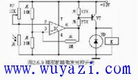
The following figure illustrates a precise dark-excitation time-delay relay switching circuit. When the illuminance decreases to the set point, the resistance of the photoresistor increases, causing the voltage at the inverting terminal of the operational amplifier IC to rise. As a result, the output of the IC turns on the transistor VT. The excitation current from VT activates the relay, closing the normally open contact while opening the normally closed contact, thereby achieving control over the external circuit.
modular rj45 jack,rj45 connector,rj45 jack,cat6a rj45,rj11 connector,rj11 jack,rj11 4p4c,rj11 modular jack
Dongguan Yiyou Electronic Technology Co., Ltd. , https://www.dsubminiature.com