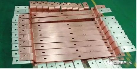
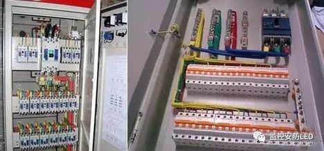
Copper busbars are widely used in electrical distribution systems to carry current and connect various electrical devices. They play a crucial role in power distribution units, where their ability to efficiently conduct electricity is essential. Many people often ask about the current-carrying capacity of copper busbars, so today we'll take a closer look at how this is calculated.
One common method for estimating the current-carrying capacity of a copper busbar is based on its width and thickness. The formula is:
- **Single copper busbar current capacity = width (mm) × thickness coefficient**
- **Double busbar current capacity = width (mm) × thickness coefficient × 1.5** (an empirical factor)
- **Copper: 5–8 A/square mm**, **Aluminum: 3–5 A/square mm**
For copper busbars at 40°C, the current-carrying capacity can be calculated using the following thickness coefficients:
- 12 mm thick → 20
- 10 mm thick → 18
- 8 mm thick → 16
- 6 mm thick → 14
- 5 mm thick → 13
- 4 mm thick → 12
So, for a single-layer copper busbar at 40°C, the formula becomes:
- **Copper busbar current at 40°C = width × thickness coefficient**
For multi-layer configurations:
- **Double layer at 40°C = 1.56–1.58 times single layer**
- **Triple layer at 40°C = 2 times single layer**
- **Quadruple layer at 40°C = 2.45 times single layer** (not recommended, better to use specialized busbars)
Also, when converting from 25°C to 40°C, multiply by 0.85. For aluminum busbars, divide the copper value by 1.3.
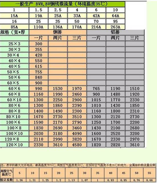
Let’s take an example: TMY 100×10
- **Single layer**: 100 × 18 = 1800 A (manual value is 1860 A)
- **Double layer**: 1860 × 1.58 = 2940 A (manual value is 2942 A)
- **Triple layer**: 1860 × 2 = 3720 A (manual value is 3780 A)
These calculations closely match manual values.
Another simple formula for rectangular copper busbars is:
- **Single busbar current = width × (thickness + 8.5)**
- Example: 15×3 at 40°C → 15 × 11.5 = 172.5 A
- Example: 100×8 at 40°C → 100 × 16.5 = 1650 A
For multiple layers:
- **Double layer = 1.5 × single layer**
- **Triple layer = 2.0 × single layer**
Now, for aluminum busbars, there's a similar approach. The rule of thumb is:
- **Thick three rows wide by ten, last four rows wide by twelve**
- **Add one to add up one by one, and the copper row is multiplied by one**
This means that as the thickness increases, the current-carrying capacity per unit width also increases. Here's a quick reference table:
| Thickness (mm) | Current Capacity (A) |
|----------------|----------------------|
| 3 | Width × 10 |
| 4 | Width × 12 |
| 5 | Width × 13 |
| 6 | Width × 14 |
| 8 | Width × 16 |
| 10 | Width × 18 |
Note: 7mm and 9mm thicknesses are not commonly available.
Example: 40×4 aluminum busbar = 40 × 12 = 480 A
Example: 60×6 aluminum busbar = 60 × 14 = 840 A
The saying “copper platoon is multiplied by a little three†means that copper busbars have about 30% higher current capacity than aluminum of the same size. So, if you calculate for aluminum first, then multiply by 1.3 to get the copper value.
Example: 50×13 → 50 × 13 × 1.3 = 845 A
Other factors like ambient temperature, number of busbars, and installation orientation (horizontal vs. vertical) can also affect the current-carrying capacity. If the ambient temperature is above 25°C or the busbars are placed closely together, it’s common to reduce the capacity by 10%. When using multiple busbars in parallel:
- 2 busbars: 80% of total
- 3 busbars: 70% of total
- 4 busbars: 60% of total
Understanding these principles helps ensure safe and efficient electrical design.
Single Type F Wall Outlet
Single Type F Wall Outlet For Power,Single Type F Wall Outlet Dimensions,Single Type F Wall Outlet Black And White,Single Type F Wall Outlet Black
Yang Guang Auli Electronic Appliances Co., Ltd. , https://www.ygpowerstrips.com