12v overvoltage protection simple circuit diagram Daquan (four analog circuit design schematics detailed)
This is a 12V/5A regulated power supply with built-in overvoltage protection. The voltage regulation is achieved using a 7805 three-terminal regulator combined with a diffuser transistor. The reference voltage at the regulation terminal is increased by a Zener diode and an LED, ensuring stable output. For overvoltage protection, a thyristor is used to short the power supply, causing the fuse to blow quickly and protect downstream components. The circuit diagram is shown below:
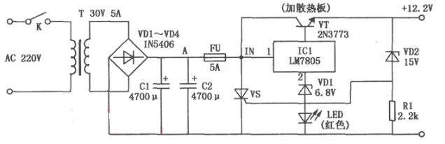
The normal output voltage of this power supply is around 12.2V. However, if the voltage regulator fails and the output rises above 15V, the Zener diode VD2 will break down and conduct. This triggers the unidirectional thyristor VS, which causes the 5A fuse FU to blow immediately, protecting the following circuits from damage.
**12V Overvoltage Protection Simple Circuit Diagram (2)**When the grid voltage suddenly increases, it can cause serious damage to household appliances such as refrigerators, washing machines, TVs, stereos, and computers. In extreme cases, it may even lead to fires and significant economic losses. To prevent this, a simple overvoltage protection device has been developed. It automatically disconnects the power when the voltage exceeds safe limits and reconnects once the voltage returns to normal, effectively safeguarding your electronics.
Working Principle
As shown in Figure 1, the circuit uses a capacitor C1 to step down the 220V AC mains voltage. The rectified DC voltage is filtered by C2 to produce approximately 12V. When the grid voltage is within the normal range, the Zener diode VDW remains off, keeping the transistor VT in the off state. This allows the bidirectional thyristor VS to remain on, enabling the appliance connected to the socket XS to operate normally.
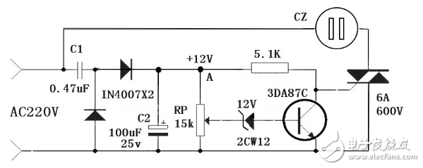
However, if the voltage rises above 250V, the midpoint voltage of RP triggers the Zener diode VDW, turning it on. This activates the transistor VT, which then triggers the thyristor VS, cutting off the power supply to the appliance. Once the voltage drops back to normal, the transistor turns off again, allowing the thyristor to turn on and restore power to the appliance.
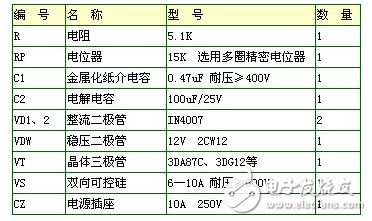
The device is easy to adjust. At 220V, you can adjust RP so that VDW does not trigger. Then increase the voltage to 250V to test whether the transistor VT turns on. Using a voltage regulator makes testing more convenient and efficient.
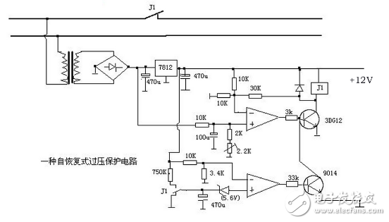
**12V Overvoltage Protection Simple Circuit Diagram (3)**Self-recovering DC 12V overvoltage protection circuit
In areas with unstable power supplies, the voltage can fluctuate significantly—sometimes reaching up to 170V during low demand and spiking above 250V at night. To protect growing numbers of home appliances, an overvoltage protector is essential.
This overvoltage protector uses the precision voltage regulator IC TL431C for accurate voltage control. A capacitor stores energy to drive the relay, resulting in very low static power consumption (only 0.1W). The circuit provides effective short-circuit protection for household appliances, making it user-friendly and reliable.
The circuit uses a capacitor-based step-down and regulated power supply. Under normal conditions, the voltage across the TL431C is below 2.5V, so it doesn't conduct, and the relay remains open. When the mains voltage reaches 250V, the rectified and filtered current increases to 3.3mA. The voltage drop across R3, the diode, and Zener (including the arc tube) is 11V and 26V, respectively. The 37V is divided by R1 and R2, producing 2.55V at point A, which turns on the TL431C. This pulls in the relay K, shorting the mains and causing the circuit breaker or fuse to trip, protecting the appliance. A small resistor is added in series with the relay contacts to limit short-circuit current and prevent contact damage.
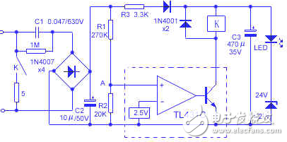
The current-limiting capacitor C1 is a 0.47μF/630V polystyrene type, chosen for its high voltage rating to prevent accidental connection to 380V lines. Relays should be selected based on power requirements, using either small or medium-sized relays like JQX13-F/024-1Z or JZC-22F/024-1Z. The 5Ω current-limiting resistor is a 5W cement resistor, and other components are selected according to the schematic. The entire circuit can be housed in a compact plastic box, with the power plug fixed at the bottom and an LED indicator visible on the surface for easy monitoring.
Three installation methods: ceiling installation, wall mounted installation, and ceiling mounted installation.
Universal Projector Mount,Universal Projector Ceiling Mount,Overhead Projector Mount,Large Projector Mount
Jiangsu D-Bees Smart Home Co., Ltd. , https://www.cI-hometheater.com