12v overvoltage protection simple circuit diagram Daquan (four analog circuit design schematics detailed)
This is a 12V/5A regulated power supply with overvoltage protection. The voltage regulation is achieved using a 7805 three-terminal regulator combined with a diffuser transistor. The reference voltage is boosted by a Zener diode and an LED, ensuring stable output. For overvoltage protection, a thyristor is used to short the power supply, causing the fuse to blow quickly and protect the downstream circuitry. Below is the circuit diagram:
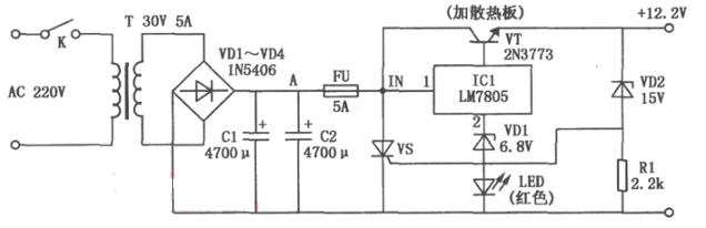
Under normal conditions, the power supply outputs 12.2V. However, if the voltage regulator fails and the output exceeds 15V, the Zener diode VD2 will conduct in reverse, triggering the thyristor VS through its gate. This causes the 5A fuse FU to blow rapidly, protecting the rest of the circuit from damage.
**12V Overvoltage Protection Simple Circuit Diagram (2)**When the grid voltage suddenly increases, household appliances such as refrigerators, washing machines, TVs, stereos, and computers can be damaged, sometimes even causing fires and significant financial loss. To prevent this, a simple overvoltage protection device has been designed. It automatically cuts off the power when the voltage goes beyond safe limits and restores it once the voltage returns to normal, safeguarding your devices.
Working Principle
The circuit works as follows: A capacitor C1 steps down the 220V AC input, which is then rectified by diodes VD1 and VD2. Capacitor C2 filters the DC output to approximately 12V. When the voltage is normal, the Zener diode VDW remains off, keeping the transistor VT in the off state. This allows the bidirectional thyristor VS to remain conducting, enabling the appliance connected to socket XS to operate normally.
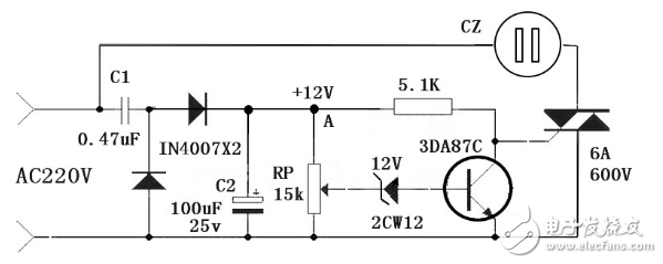
However, if the grid voltage rises above 250V, the midpoint voltage of RP triggers the Zener diode VDW, turning it on. This activates the transistor VT, which lowers the gate voltage of the thyristor VS, causing it to turn off. As a result, the appliance loses power and stops working, preventing damage. Once the voltage drops back to normal, the transistor turns off again, allowing the thyristor to conduct and restore power.
Adjusting the variable resistor RP allows you to set the threshold at which the protection activates. When testing, ensure that the Zener diode doesn’t trigger at 220V but does so at 250V. This makes the device easy to use and highly effective for home appliances.
**12V Overvoltage Protection Simple Circuit Diagram (3)**Self-recovering DC 12V overvoltage protection circuit
In areas with unstable power supply, the voltage fluctuates significantly—sometimes reaching up to 170V during low load and exceeding 250V at night. To protect growing numbers of household appliances, an overvoltage protector is essential.
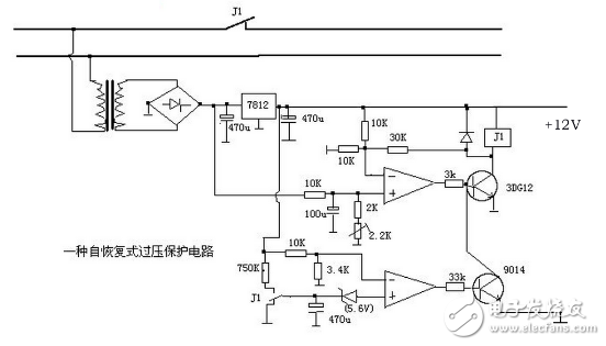
This overvoltage protector uses the precision voltage regulator IC TL431C for accurate voltage sensing. A capacitor stores energy to activate the relay, resulting in very low static power consumption (only 0.1W). It effectively protects against short-circuit power surges, making it user-friendly and efficient.
The circuit uses a capacitor-based step-down and regulated power supply. Under normal conditions, the control voltage of the TL431C is below 2.5V, so the circuit doesn't conduct, and the relay remains open. When the mains voltage reaches 250V, the rectified and filtered current becomes 3.3mA. After passing through R3, the diode, and Zener (including the arc tube), the voltage drop is 11V and 26V respectively. The 37V is divided by R1 and R2, giving 2.55V at point A, which turns on the TL431C. This activates the relay K, shorting the mains and tripping the circuit breaker or blowing the fuse, thus protecting the appliances.
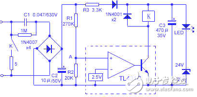
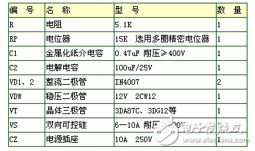
The current-limiting capacitor C1 is selected as a 0.47μF/630V polystyrene type to handle high voltages safely. To avoid accidental connection to 380V, it must have sufficient voltage rating. Relays should be chosen based on power requirements—small or medium-sized relays like JQX13-F/024-1Z or JZC-22F/024-1Z are recommended. A 5Ω 5W cement resistor is used in the contact loop to limit short-circuit current. All components are placed in a small plastic box, with the power plug fixed at the bottom and an LED exposed on the front for visual indication.
Cross cut electric suspension, minimalist design, suitable for multiple scenarios, creating a convenient working environment for you.
Motorized Projector Mount,Motorised Projector Mount,Motorized Projector Screen Mount,Motorized Recessed Projector Mount
Jiangsu D-Bees Smart Home Co., Ltd. , https://www.cI-hometheater.com