How to extend battery life with dual processor applications
In the face of the need to extend battery life, many system designers believe that a single chip consumes less power than two chips. The reason seems simple: inter-chip communication consumes more power than a single chip operation, and there are more transistors on both chips, so there is more leakage current than a single chip with the same function. But power-saving technology has given this traditional view a head start.
DSP designers integrate more functions, such as accelerators, communication modules, and network peripherals, onto the DSP chip, making the chip more useful to engineers. But this more powerful chip consumes more power than the task requires when doing simple housekeeping or monitoring tasks. In many cases, designers can't just enable the features of the required parts of the DSP chip.
In some applications, a microcontroller (MCU) can perform the same system monitoring tasks while consuming less power than the DSP. Therefore, the architecture of the two-chip: DSP and MCU are also feasible. Therefore, using one low-power DSP as the main processor and another low-power MCU as the system monitor can extend the battery life consumed by a single DSP to accomplish the same task. To help save power, engineers should consider the following factors when choosing a DSP:
Look for larger amounts of on-chip memory. DSPs always consume more power when accessing off-chip memory. External DRAM storage requires constant power consumption, which consumes battery power.
Select a DSP that can start and shut down the peripherals. There are DSPs that automatically power down inactive on-chip peripherals, which provides multiple levels of control and power savings.
Choose a DSP that can achieve multiple standby states at different power levels. Multiple power supplies save more power.
Choose a DSP that provides development software that optimizes power usage and reduces power consumption. Tools should allow developers to easily change the voltage and frequency of the chip, manage power states, and help them evaluate and analyze power consumption information.
MCU consumes less current
In MCUs in some applications, low-power semiconductor processes reduce transistor leakage current and help chip designers optimize low-power operation. Unfortunately, low power processes limit MCU performance. For example, a Texas Instruments MSP430 MCU consumes 500nA in standby mode with a maximum clock frequency of 16MHz. The TMS320C5506 DSP runs at a maximum clock frequency of 108MHz and consumes 10μA in standby mode. This indicates that it consumes 20 times more current than the MSP430.
From the previous development history, the internal MCU peripherals have been controlled by software, which indicates that the CPU is always active. But new interrupt-driven peripherals require less software overhead, allowing the MCU to remain in standby mode most of the time. Taking internal analog-to-digital converter (ADC) hardware as an example, it automatically scans input channels, trigger transitions, and performs DMA transfers to handle received data sampling tasks. As a result, the ADC runs almost spontaneously, and the CPU only provides service in a small amount of time, and the MCU saves power.
Multiple clocks reduce power requirements
The MCU's clock system design also helps reduce power consumption. The circuit diagram in Figure 1 shows two clocks run by a single crystal. MCUs typically use a 32kHz crystal, but do not necessarily generate an internal clock signal, a system clock (MCLK), and an auxiliary clock (ACLK) signal. Typically, the crystal only generates the ACLK signal. The MCU's low-power peripherals use a 32kHz auxiliary clock that simultaneously drives the MCU's real-time clock. The high-speed digitally controlled oscillator (DCO) generates the system clock signals for the CPU and high-speed peripherals.
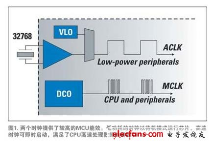
The DCO can generate clock signals in several ways, each with different performance and power characteristics. From low to high power consumption, these clock modes feature ultra low power oscillator (VLO), 3kHz crystal to DCO. To reduce power consumption, designers use the lowest clock (VLO or 32kHz crystal) in idle mode, and implement high frequency DCO when the application requires active processing of the CPU. The DCO can be active and reach full stability in less than 1μs. This "on-the-fly" capability saves time and power. Note that using a low frequency, low power clock during active processing consumes more power than switching to a faster clock. In higher power active mode, the low frequency clock allows the CPU to spend more time on a particular task.
In addition to using low-speed clocks to save power on some peripherals, the MSP430 MCU also provides an ultra-low-power oscillator to generate the ACLK signal. In its standby power mode of operation (LPM3), the MSP430 MCU typically consumes less than 1 μA during ACLK operation and all interrupt enable states. Therefore, a low-power MCU consumes less power than a DSP while maintaining a real-time clock or managing battery charging. Moreover, handing these tasks to the MCU can also free the DSP to perform its own signal processing tasks.
Power consumption is very effective
Engineers can see the dual processor design achieves outstanding results. Imagine a system that relies on high-end DSPs to handle monitoring tasks. The processor will soon run out of a 2,500 mAh NiMH AA battery. If the average current consumption is 10 mA, the two series cells will be exhausted in 10.5 days. Dual processor applications reduce current to 1mA and extend the battery to 120 days.
In order to reduce power consumption in a dual processor system, some of the system or monitoring functions that can be handled include:
Real time clock maintenance
Power sequencing
Power monitoring and reset
Keyboard or human interface management
Battery management
Display control
Manage DSP power
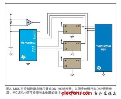
Many DSPs require multiple power "rails" that must be applied in a fixed sequence to ensure proper operation of the DSP and peripherals. Typically, these rails power both core (CPU) and DDR memory and I/O devices. Although dedicated devices can apply voltage to the DSP chip in a fixed order, they cannot perform other functions. Smaller, low-power MCUs can sequence and monitor supply voltages and perform power control tasks (Figure 2). In this example, the software starts three power regulator circuits in the proper order. The MCU uses its internal ADC to detect when each power rail reaches the proper voltage. When the total circuit does not require a DSP chip, the MCU can turn off the regulator to turn off the DSP.
In fact, the MCU can communicate directly with the voltage controlled oscillator to control the voltage and frequency of the DSP, or communicate with the PLL to control the clock frequency of the DSP. Therefore, when the DSP completes computationally intensive tasks, the MCU can adjust the clock to turn the DSP into standby mode to save power.
Bidirectional monitoring allows the MCU to "detect" the DSP to understand its busy state. In this mode, the MCU operates as an intelligent controller. On the other hand, the DSP can read and write operations to the MCU. Therefore, the DSP can notify the MCU to reduce or increase the DSP clock according to the needs of the application.
Designers can also get more benefits by using MCUs to accomplish other tasks that DSPs typically implement in a single processor system. For example, when dealing with keyboard operations, MCUs consume less power than DSPs. The MCU sends an interrupt signal to the DSP only after detecting the button or releasing the button. This approach helps to avoid excessive current consumption caused by keystrokes, which often occurs in some handheld devices. To further relieve the load on the DSP chip, the monitoring MCU can provide:
Segment LCD driving circuit
Standard SPI, UART, and I2C ports
Interface for RF communication peripherals
Battery management circuit
General purpose I/O port
For each of the other peripherals mentioned above and previously mentioned, the MCU can be "auto-started" from a low power mode. Therefore, the MCU does not continuously poll the peripherals to determine which service is needed, nor does it consume the most power to perform the task. The peripherals will start as needed.
Every milliwatt in a low-power portable application is invaluable. Finally, the designer must determine whether to use one or two processors in the application based on a comprehensive consideration of calculations, measurements, and functions and running the DSP or MCU.
Recessed 1x4 Troffer Lights and LED Flat Panels.Fluorescent versus LED recessed troffers.When searching for your 1X4 Led Troffer , you'll also find that we offer various light fixture styles.Our inventory of fluorescent 1X4 Troffer Lights are affordable and easy to install.Energy efficient 1X4 Recessed Troffers for recessed ceiling commercial office lighting applications with a stylish design and robust construction.
1x4 Troffer Lights
1X4 Led Troffer,1X4 Troffer Lights,1X4 Recessed Troffers,1X4 Troffers
Shenzhen Bbier Lighting Co., Ltd , https://www.chinabbier.com