High-voltage starting circuit and control strategy for automotive HID headlamps
Central issue:
HID headlamps are an important choice for next-generation automotive headlamps due to their high luminous efficiency, good color rendering, long life and many other advantages.
Introduce a new type of HID headlight start-up circuit that reliably achieves fast lighting and extends lamp life
solution:
The controller quickly charges the Cc and current connection capacitors through a 400 V constant voltage closed loop control.
Using current integration to achieve low frequency AC square wave lighting to avoid the danger of DC and high frequency AC lighting
High Intensity Discharge (HID) lamps are a new generation of energy-saving lamps that have been widely used in transportation, municipal, and factory lighting. Automotive high-intensity gas discharge headlamps have many advantages such as high luminous efficiency, good color rendering, long life, etc., and have been highly valued by the automotive industry in various countries.
Most electronic ballasts use a DC converter to boost the DC voltage of 12V, and the inverter circuit supplies AC to the lamp to avoid excessive burnout of the single-sided electrode. The efficiency of the front stage directly affects the efficiency of the system. Therefore, the boost DC link must be properly designed. Because the car headlights require a quick start and a quick instant start of the heat. The starting voltage required for cold light start-up is typically greater than 13 kV, and the starting voltage required to restart the lamp after extinguishing is required to be as high as 23 kV. Therefore, the output voltage of the HID headlamp start-up circuit should have sufficient amplitude and width and a wide voltage range.
This paper proposes a new type of starting circuit, and uses current integration as a criterion to identify the hot and cold start, which reliably achieves rapid lighting and extends the life of the lamp.
Comparison of common high voltage starting circuits
During startup, the electronic ballast has to undergo three stages of high voltage breakdown, current connection, and preheating. The high voltage start-up circuit is the basis for the instant illumination of the HID headlamps. However, the inertia and filtering delay after glow discharge make it difficult for the DC converter and the detection loop to have a fast response speed. Therefore, a current take-over circuit as shown in Fig. 1 is needed, which can utilize the energy stored in advance by the capacitor. Provide a large instantaneous current (about 300ms) for the lamp to ensure a reliable transition of the arc. Generally, the high voltage generating circuit has the following types:
This article refers to the address: http://
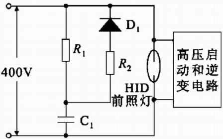
Figure 1 current connection circuit
a. Single stage boost circuit
This circuit generally requires a high turns ratio. Since the high voltage coil flows through the lamp current, the wire used cannot be too thin, which increases the volume of the high voltage transformer. The parallel connection can be used to make the high-voltage side coil wire thinner, but the lamp needs to be connected in series with another ballast inductance, so that the ballast system is also bulky.
b. Two-stage boost circuit
With this circuit, the high-voltage side winding acts as a ballast inductor while generating high voltage, which can reduce the volume and weight of the system, as shown in Figures 2 and 3. The difference between Figure 2 and Figure 3 is that the former uses a two-stage transformer, which is bulky. The circuit of Figure 3 uses only one step-up transformer, but the front stage uses a voltage doubler rectifier circuit, which can reduce the turns ratio of the transformer. Will increase the size of the transformer. Figure 4 shows the circuit we used. Since there is only one primary transformer, the volume is greatly reduced.

Figure 2 High-voltage startup circuit with two-stage step-up transformer
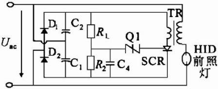
Figure 3 Single-stage step-up transformer boost circuit with voltage doubler rectification
Principle analysis of high voltage start-up circuit
In the voltage doubler rectifier circuit, the current path in both directions of the secondary side of the transformer exists, and the flyback portion of the circuit is no longer a flyback converter. In the startup phase, the control program performs a 400V constant voltage closed loop on the terminal voltage of the bus capacitor C1 of the full bridge inverter circuit, that is, the bus voltage of the rear H bridge. The voltage doubler rectified output voltage is 1200V. The capacitor Cc is charged through R1 and R2, and the voltage of the Cc section is gradually increased. If its terminal voltage can reach 600 V, the discharge tube breaks down, Cc discharges, and energy is coupled to the secondary side to generate high voltage. If the double-voltage rectified output voltage is not high enough, the partial pressure of the resistors connected in parallel with Cc is less than 600V due to the partial pressure of R1, R2 and R3, and the discharge tube cannot be broken. Even if the voltage of the voltage doubler rectification is sufficiently high, if the ratio of R3 to R1+R2 is not large enough, a breakdown voltage of 600V cannot be generated.
Once the terminal voltage of Cc breaks down the discharge tube, the energy in Cc is transferred to the secondary side of the high voltage transformer, and a high voltage is generated at the lamp end. The voltage value is the inductance and capacitance of the secondary side of the transformer, the lamp state and the varistor and the line. The time constant of the loop formed by the resistor is determined.
Start-up phase control
In order to achieve reliable start-up, the controller quickly charges the Cc and current-connected capacitors through a 400 V constant-voltage closed-loop control. If the voltage is too low, the startup may be slow, or the energy of the circuit may not be sufficient after startup, and the startup fails. In order to avoid excessive burning of the single-sided electrode, it is necessary to avoid firing from the single-sided electrode each time. A random selection subroutine for starting direction is set in the program.
At the same time as the voltage closed-loop control, the program continuously detects the current. Once the current reaches the set value, it confirms that the startup is successful and enters the maintenance phase (Warm-up) phase. The time of this phase is tpre. The main task is to preheat the arc. In order to prevent the excessive burning of the single-sided electrode caused by DC lighting and the zero-crossing of the zero-crossing under high-frequency AC, this paper uses a current integration method to realize the low-frequency AC square wave. The current integral must satisfy: During the Warm-up period, the current sampling value is added after each interrupt occurs. Once the sum is reached, the sum is cleared and the inverter bridge is flipped to switch to the lower half of the wave. Repeat the above process until the end of the half wave, entering the power diminishing transition phase. The advantage of this control is that the lighting temperature can be automatically recognized to provide an initial basis for subsequent control.
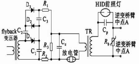
Figure 4 High voltage start-up circuit used in the test
High voltage generating circuit experiment and waveform
Figure 5 uses a 3x voltage rectification circuit. The rated breakdown voltage of the discharge tube is 600V, the turns ratio of the high voltage package is 1:50, and the breakdown voltage of the discharge tube is 600V. The experimental waveform is shown in Figure 6.
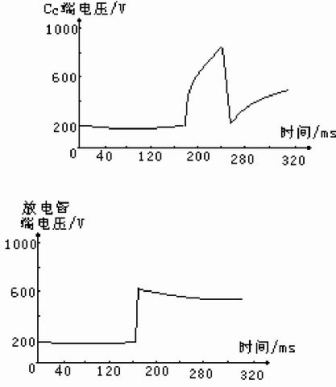
Figure 5 Start instantaneous capacitor Cc terminal voltage and discharge tube terminal voltage
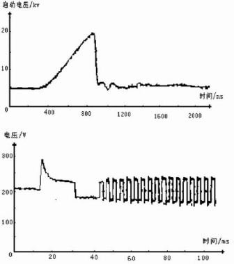
Figure 6 Cold light starts high voltage and working voltage waveform
The switch experiment was to develop a programmable controller (PLC) program to verify the reliability of the circuit and control strategy for testing the switching reliability of electronic ballasts. The switch experiment was carried out for 3 hours, with a total of 40,000 switches, all of which were reliably started.
Conclusion
The high voltage generating circuit used in this paper is small in size, wide in starting voltage range and reliable in starting. The control program fully considers the characteristics of the AC lamp, which can minimize the one-side burning of the electrode and prolong the service life of the headlamp.
To satisfy the increasing demand of PoE for Fast Ethernet (FE) networking, N-NET has developed this series of Unmanaged/Managed POE Switch. It fully complies with IEEE 802.3af standard and can allow you to expand your network to areas with no power line or output. The PoE feature enables the switch an efficient and cost-effective solution for SMB, SOHO or other similar fields to deploy the PoE network for the wireless access points, IP-based surveillance cameras or IP phones anywhere easily and efficiently. N-NET also develop Fast Ethernet or Gigabit Ultra PoE Managed Switches with LCD Touch Screen featuring N-NET intelligent PoE functions to improve the availability of critical business applications.
POE Switch
POE Switch,Gigabit POE Switch,Managed Fast Ethernet POE Switch,Unmanaged Fast Ethernet POE Switch
Shenzhen N-net High-Tech Co.,Ltd , http://www.nnetswitch.com