Study on changing nanosecond pulse driving waveform to improve the light-effect of plasma display panel during maintenance period
1 Introduction
Although PDP has natural advantages in imaging comfort, dynamic effects, contrast, color reproduction, depth of field, etc., the luminous efficiency is not high, and the power consumption of the whole machine is too large, which is the bottleneck of its application to 3D display. The light efficiency of PDP is very low, only 1 ~ 2lm / W, mainly because the conversion efficiency of electrical energy to ultraviolet light in discharge cells is very low (only 3% ~ 5%).
In recent years, in order to improve the display efficiency of PDP, many organizations have done in-depth research and achieved some results. Among them, in the research of changing the driving method, the parameters such as the amplitude, waveform and frequency of the driving voltage are mainly changed. This paper focuses on improving PDP light efficiency from pulse-driven mode.
2 Theoretical basis for improving the light efficiency of PDP by rising edge of fast pulse
2. 1 Experimental basis for improving the UV light effect of dielectric barrier discharge by pulse driving
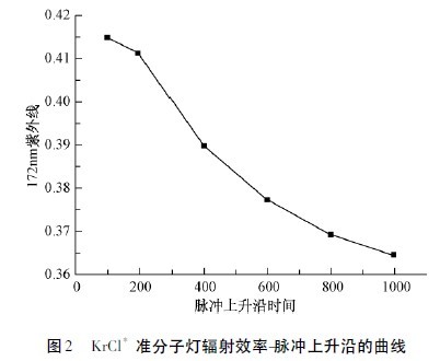
Pulse-driven xenon lamps have been shown to significantly improve light efficiency and energy efficiency relative to sinusoidal signals. Figure 1 shows the UV radiation efficiency change of a pulsed and sinusoidal driven xenon lamp. It can be seen that the radiation efficiency of the pulse-driven xenon lamp increases significantly with the increase of gas pressure than the sinusoidal drive mode. It is about 2.5 times the sinusoidal mode at 600 Torr. This is mainly because the higher pressure pulse mode improves the effective collision rate of Xe* into Xe*2. In addition, studies have shown that pulses with faster voltage rising edges can significantly increase the radiation efficiency of KrCl* excimer lamps. The faster the rising edge, the higher the ratio of electrons to the total energy in the ionized gas under the action of a high reduced electric field (E/n), and the collision cross section of electrons and atomic molecules is reduced [3]. In Figure 2, as the rising edge of the voltage increases, the 172 nm UV radiation efficiency increases significantly. Xenon lamps, KrCl* excimer lamps, and PDPs are all dielectric barrier discharges. Assuming that the fast pulse drive can improve the thermal effect of the cation cation of the dielectric barrier discharge of the PDP unit, the influence of the rising edge of the voltage and current and the pulse width on the luminous efficiency can be sought by changing the driving mode of the PDP, and the optimum value is obtained to improve the PDP light. Efficiency and efficiency.

2. 2 PDP unit gas discharge reaction process
Each color pixel of the PDP includes front and rear substrates, a pair of ITO transparent electrodes on the front substrate, and metal electrodes under the ITO electrodes. A transparent medium is produced in parallel with the electrodes. The lower layer is the MgO layer used to reduce the operating voltage and protect the medium. On the rear substrate, the lowermost layer is the address electrode, which is spatially orthogonal to the front substrate electrode. A vacuum ultraviolet photoluminescent phosphor is applied to the bottom and sides of the barrier between the two electrodes. RGB trichromatic phosphors are applied to the adjacent three barriers to form a color pixel filled with Ne-Xe Penning working gas.
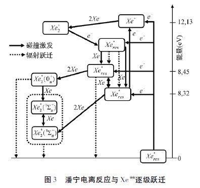
As shown in Figure 3, when a dielectric barrier discharge occurs between electrodes under a certain external voltage, the direct ionization of Ne atoms produces Ne + which in turn produces a large number of two-body collision reactions:
e + Ne* → Ne + 2e (sequential ionization) (1)
e + Ne = Nem + e (meta-stable excitation) ( 2)
Where Ne* represents the excited state of Ne and Nem is the metastable excited state of Ne. Since the metastable energy level of Nem ( 16. 62 eV) is greater than the ionization energy of Xe ( 12. 27 eV). The metastable atom Nem and Xe undergo panning ionization:

The collision of high-speed electrons with Xe + produces an excited state Xe** ( 2P5 or 2P6), and the instability of the energy state causes it to produce a stepwise transition, ie
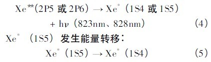
Where 1S4 is the 147 nm ultraviolet light that causes the PDP to emit light when the atomic Xe resonant excitation level resonance transitions to the Xe ground state, ie:

The Xe resonance state is formed by the Xe*2 dimer state, which is the 172 nm VUV ray generated by the radiation in Fig. 3.
2. 3 Effect of voltage rising edge on gas density in reaction process
For the coplanar electrode, the atomic state Xe excitation occurs far away from the phosphor, and the 147 nm ultraviolet radiation generated by it is almost entirely trapped inside the discharge cell; and the effective lifetime of Xe*2 is as long as several μs. The 173 nm VUV ray generated by Xe*2 dimerization produces an important contribution to the luminescence of the phosphor. Therefore, one of the ways to improve the efficiency of the PDP unit is to choose the driving method to direct more energy to Xe*2.
The discharge plasma in the PDP unit is a typical non-equilibrium plasma. The fast pulse rising edge may cause the electron temperature and ion temperature difference to increase, resulting in more effective collisions, and the particles can be excited more efficiently. Moreover, during the fast pulse process, the ions are heated for a shorter period of time, and the phenomenon of absorbing energy and radiating infrared light is improved. Thereby improving the conversion efficiency of electric energy to ultraviolet light energy. Increasing the rising edge of the PDP driving voltage can effectively stimulate the generation of more high-energy electrons while maintaining the Ne, Xe plasma at a lower temperature, making the three-body collision process more efficient and beneficial to the generation of Xe*2.
3 experimental framework
3. 1 Experimental platform and power parameters
The self-developed PDP nanosecond pulse drive test platform frame is shown in Figure 4. The nanosecond pulse drive source is shown by a black frame and consists of three parts: control signal circuit, signal isolation amplifier circuit and high voltage pulse main circuit. The control signal circuit is powered by the isolated switching power supply to the CPLD, and the control signal is implemented by the VIOLOG language. The signal amplifying circuit is to receive the illuminating signal through the optical fiber with strong isolation interference, isolate the electrical connection, and then perform signal amplification to drive the fast rising edge MOSFET.

The power output parameters are: Voltage: 0 ~ 400V Rising edge 45 ~ 500ns Current: 0 ~ 30A Resistive load voltage fastest rising edge 50ns
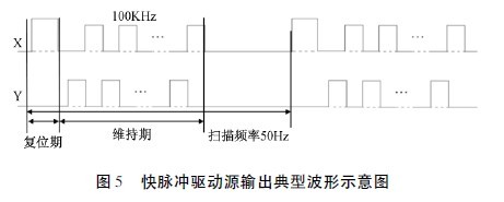
Scanning frequency: 50K ~ 1000KHz, subfield frequency: 0 ~ 200Hz, generate PDP molecular field maintenance period driving waveform, only work in the maintenance period in one scan cycle. It behaves in the form of a periodic pulse array. A typical drive waveform is shown in Figure 5:
3. 2 experimental plan
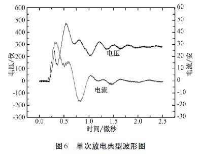
This study focused on improving the white light efficacy of the PDP, thus simplifying the driving method of the PDP and intercepting the maintenance phase of the ADS molecular field drive. The power and efficacy measured in this driving mode reflect the trend and rate of change during the maintenance period. Therefore, in this paper, the measured quantities are converted into reference quantities of unit "1". From Fig. 6, the dielectric barrier discharge characteristics of the PDP unit can be seen. When the current occurs in the sudden change of the applied electric field, the current oscillation tends to zero after the insulation of the low pressure chamber is restored.
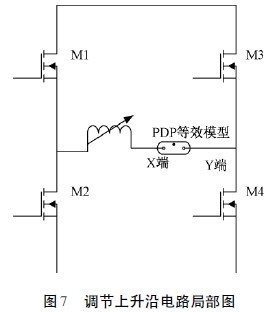
By stringing the adjustable inductor L into the PDP load terminal in Figure 7, the PDP voltage rising edge in Figure 6 can be changed approximately without loss. The pulse width in Figure 5 can be changed by changing the control signal. Repeat the above test by changing the pulse width, testing the screen illumination, the value of the infrared light intensity, and changing the value of the voltage rising edge at the same rising edge. The measured infrared intensities at 823 nm and 828 nm reflect changes in 147 nm UV radiation during the change in pulse width and rising edge.