LED COB thermal analysis
The so-called COB package (Chip on Board) means that the LED chip is directly packaged on the substrate. That is to say, N LED chips are bound to a metal substrate or a ceramic substrate to become a new LED light source module. Usually according to the power supply design requirements, multiple small chips are used together to form a high-power light source module, and with the design of the secondary lens and the heat-dissipating housing, the power supply efficiency, heat dissipation performance and low cost are developed. lighting device.
As we all know, because the junction temperature of the chip directly affects the LED light extraction efficiency, color shift and device lifetime parameters, how to improve the heat dissipation capability of the packaged device and reduce the chip temperature has become a key technical link in the COB structure design. For the packaging heat dissipation problem of high-power COB LEDs, it is usually solved by selecting a suitable substrate by rationally arranging a plurality of LED chips. This paper is mainly for the thermal analysis of COB modules corresponding to the power supply developed by Yuanhui Optoelectronics. The effects of LED chip array, ceramic substrate (Al2O3 substrate, AlN substrate) and metal substrate (aluminum substrate, copper substrate) on the chip temperature were discussed.
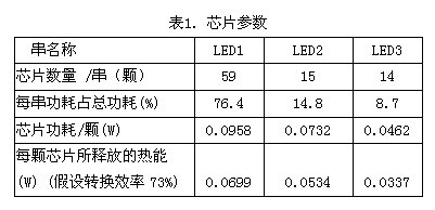
The dynamic control switch developed by Yuanhui Optoelectronics recombines the power supply of the LED serial connection mode, and divides 88 chips into 3 strings (LED1, LED2, LED3), as shown in Figure 1.
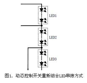
Among them, there are 59 in LED1, the power consumption is 76.4%; 15 in LED2, the power consumption is 14.8%; 14 in LED3, the power consumption is 8.7%. Assuming the total power consumption of 88 chips is 7.4W, then It can be calculated that the power consumption of each chip of the three strings of chips is as shown in Table 1. It can be seen that in LED1, the power consumption of each chip is: 0.0958W; the power consumption of each chip in LED2 is: 0.0732W; the power consumption of each chip in LED3 is: 0.0462W. Obviously, this The single-chip power consumption of the three-string chip is not equal, and the single-chip power consumption of the LED1 is twice that of the LED3. This may cause the junction temperature of the chip to be different, resulting in different lifetimes. Below we analyze how to reduce the temperature difference caused by the uneven distribution of power consumption of the chip.
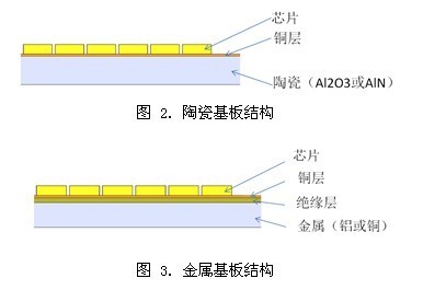
As can be seen from Figure 1, 88 chips are connected by a single string, and at the same time, four wires are connected to the periphery of the chip array combination for use with the power connection. It is assumed here that the ceramic substrate is constructed (see Figure 2 for the structure): the size of the ceramic substrate is 10mm x 10mm x 0.5mm (wherein the center 5mmx5mm is the area occupied by the chip, and the area around the 2.5mm width is required for the placement of 4 pads) ). There is a layer of copper (thickness 30um) on the top; the structure of the metal substrate (see Figure 3 for structure): the substrate size is 10mm x 10mm x 1mm, the thickness of the insulation layer is 75um, the thickness of the copper layer is 35um, and the chip used is CREE DA3547 .
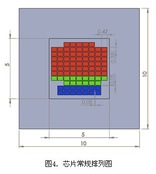
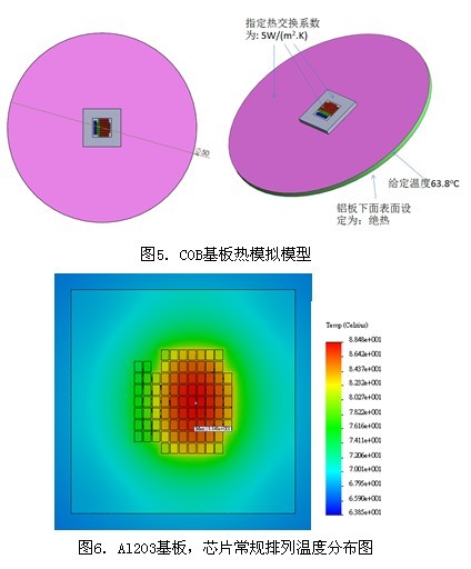
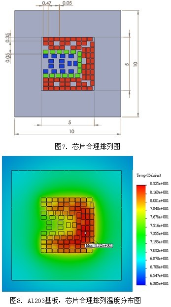
We first arrange the chips according to the conventional method. As shown in Figure 4, 59 high-power chips in LED1 are shown in red, 15 chips in LED2 are shown in green, and 14 low-power chips in LED3 are in blue. Said. Then the COB substrate is fixed on an aluminum plate (thickness 1.2mm, diameter 50mm), which is mainly used to replace the heat-dissipating shell of the bulb (Fig. 5.). We assume that the edge temperature of the aluminum plate is 63.8 degrees Celsius (equivalent to a bulb lamp). The temperature of the outer casing), assuming that the surface of the aluminum plate corresponding to the chip and the outer surface of the chip have an external heat exchange coefficient of 5 W/C.m2, the ambient temperature is 25 ° C, and the other surfaces are insulated. The thermal power consumption parameters of the chip are shown in Table 1. Then we use SolidWorks Simulation to simulate and calculate the temperature distribution of the conventionally arranged chip on the Al2O3 substrate. As can be seen from Figure 6, the maximum temperature of the chip is 88.5. oC (in the LED1 string), the minimum temperature is 75 oC (in the LED3 string), so there is a temperature difference of 13.5 oC between different chips on this group of COB substrates, which will lead to different life spans.
From the temperature profile (Figure 6), we can think of a more reasonable chip layout diagram, which is to place the high-power chips in the LED1 string in the low temperature outer ring as much as possible, and the LED3 string low-power chip is placed in the high temperature. Circle, at the same time should consider the chip arrangement to meet the power supply design requirements of Figure 1, so we have a more reasonable arrangement as shown in Figure 7. Similarly, we calculated the temperature distribution of this arrangement on the Al2O3 substrate (Fig. 8.). The results show that the maximum temperature of the chip is 83.3 oC (in the LED1 string) and the lowest temperature is 74.9 oC (in the LED3 string). Therefore, there is a temperature difference of 8.4 degrees between different chips on the COB substrate, which is 5 ° lower than the conventional arrangement.