MOS tube (field effect transistor) amplifier circuit and principle
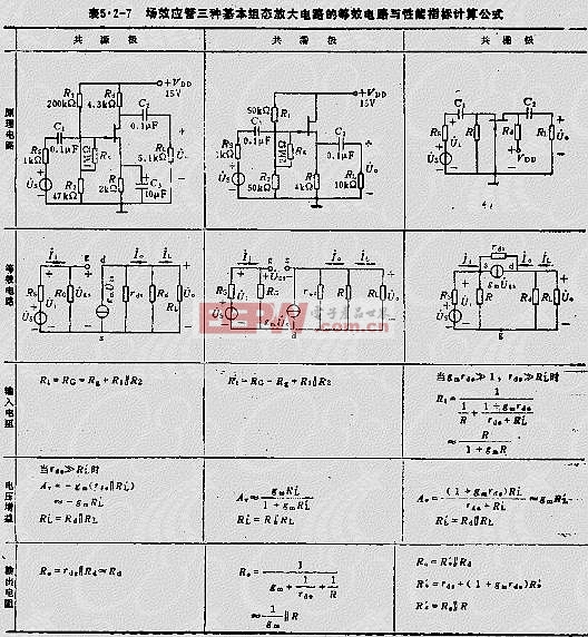
The field-effect transistor (FET) amplifier is a voltage-controlled device that boasts high input impedance and low noise, making it a popular choice in electronic circuits, particularly in preamplifiers where these features are highly desirable. Depending on the type of FET—junction field-effect transistor (JFET) or insulated-gate field-effect transistor (IGFET)—the corresponding FET amplifier can be formed. Below is an example providing the equivalent circuit and performance index calculation formulas for the three basic configurations of amplifiers, as seen in Table 5.2-7. The accompanying image illustrates how the FET exhibits a control effect similar to that of a transistor, allowing for the creation of three fundamental amplifiers: common source, common drain, and common gate.
1. Bias Circuit: Since different types of FETs operate within the amplification region, their gate voltages require different polarities. For instance, JFETs necessitate the gate-source and drain-source voltages to have opposite polarities, whereas MOSFETs require the same polarity between the gate-source and drain-source voltages. The gate bias polarity for depletion-mode MOSFETs can be positive, zero, or negative.
Based on these characteristics, there are primarily two types of bias circuits for single-supply amplifiers: (1) Self-bias circuit—used for JFET and depletion-mode MOSFET amplifiers. Figure 5.2-6 demonstrates an N-channel JFET self-biasing circuit, where the gate-source voltage (UGS) equals RID. (2) Hybrid bias circuit—employed in various FET amplifiers. The hybrid bias circuit for an N-channel enhancement-mode MOSFET amplifier is shown in Figure 5.2-7.
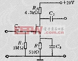
Figure 5.2-6: Self-biasing circuit with gate-source voltage (UGS) = RID
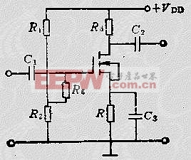
Figure 5.2-7: Hybrid bias circuit
2. Equivalent Circuit and Performance Index Calculation Formula for Field Effect Transistor Three Basic Configuration Amplifiers (as shown in Table 5.2-7)
Gate-source voltage:
When designing FET-based amplifiers, understanding the biasing techniques is crucial for achieving optimal performance. The self-biasing method is straightforward and effective for many applications, but hybrid biasing offers more flexibility, especially when dealing with complex circuits. The use of high-quality components like crystal oscillators, MOSFETs with imported FETs, and photocouplers ensures the reliability and precision of the final design.
Additionally, the field effect transistor's ability to function as a common source, common drain, or common gate amplifier makes it a versatile component in modern electronics. Whether you're working on audio equipment, RF devices, or any other application requiring high-fidelity signal processing, the FET amplifier remains an essential building block. By carefully selecting the biasing scheme and utilizing advanced components, engineers can create efficient and robust circuits tailored to specific needs.
In conclusion, mastering the principles behind FET amplifiers and their associated biasing methods is vital for anyone involved in electronic design. The combination of theoretical knowledge and practical implementation skills allows for the development of cutting-edge solutions that meet today’s demanding standards. Whether you're a hobbyist tinkering with new projects or a professional engineer tackling complex challenges, the field-effect transistor continues to play a pivotal role in shaping the future of technology.
Wuxi Ark Technology Electronic Co.,Ltd. , https://www.arkledcn.com