Design of Vehicle Information Acquisition System Based on Serial Communication
This paper introduces an in-vehicle information collection system for electric vehicles: multi-slave machine collects information, and multi-machine communication using serial communication between the slave and the host, and then the host sends the communication data to the LCD display. It solves the difficulty of the vehicle information and the complicated wiring of the body and the difficulty in collecting data.
This article refers to the address: http://
1 Introduction
As an important communication technology, serial communication has been widely used in the field of PC communication and industrial field control online detection [1]. The vehicle information collection system designed in this paper is a structural system including data acquisition, data transmission and data display. It is a design process for collecting, transmitting and displaying the vehicle information of a new type of electric vehicle: the vehicle information passes the sensor (analog form) The switch form is taken from the MCU, the main MCU and the MCU through the serial communication for data transmission, and the host sends the data to the LCD panel for display.
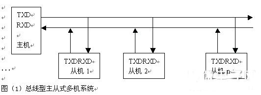
2 bus type master-slave multi-machine system
Considering a large number of in-vehicle information and serial port multi-machine communication capabilities involved in electric vehicles, the design uses a bus-type master-slave multi-machine communication mode, and the standard bus for data transmission is selected as the most common and practical. RS-485. The bus-type master-slave multi-machine communication system mode is as follows:
The serial communication protocol is not introduced here.
3 car information acquisition system hardware design
The object studied by this system is the vehicle information of an electric car. The author divides the information into two categories: analog quantity and switching quantity. The analog quantity includes: battery pack (battery) temperature, battery pack (battery) voltage, battery pack (battery) capacity, vehicle speed (mileage), total current, etc.; switch quantity refers to various operating states, including: lamp (series) Status, gear switch, brake status, limit switch status, etc.
Due to the large amount of information involved and the wide range of distribution around the body, the author uses AMOS's single-chip microcomputer - ATMEGA8L. This is a small-sized microcontroller with sufficient acquisition and communication capabilities: in terms of acquisition, it contains 8 channels of A/D conversion and up to 23 programmable I/O ports; in terms of data communication, it contains one The programmed serial USART interface supports synchronous, asynchronous and multi-machine communication automatic address recognition [3]. An important advantage of ATMEGA8L over 8051 or other microcontrollers is that the peripheral circuits required by the microcontroller are relatively simple (taking into account the body wiring, the simpler the circuit, the better). The LCD display module uses the dot matrix liquid crystal of MGLS240128T with built-in T6963C. It is characterized by simple interface circuit with single-chip microcomputer and powerful display function.
The hardware framework of the vehicle information collection system designed in this paper is as follows:
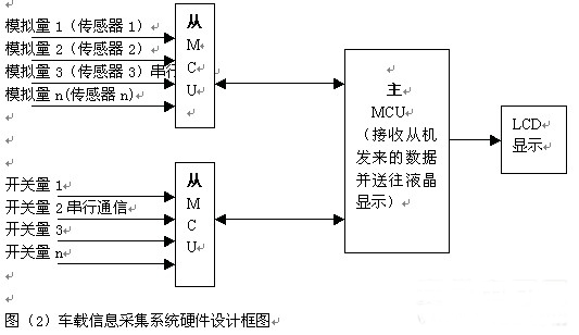
The analog quantity is sampled by a specific sensor, converted into a voltage signal and enters the A/D channel of the slave. The slave performs A/D conversion and stores the data; the switch sends the level signal to the I/O port of the slave through the relay. The slave also processes the signal. Data is transmitted between the master and the slave through serial communication, and the host sends reasonable data to the LCD for display.
4 car information acquisition system software design
The multi-machine communication protocol based on serial communication can be performed as follows: 1. All slaves are in the listening state. 2. The host first sends a synchronization character (ie, the start character, here is E8H), and then sends an identifier (defines different values ​​according to the information category, such as the identifier of the current value is defined as 14H), and converts the communication state. Is the receiving status (RXD=1). 3. When the slave defined by the identifier (such as slave 1 responsible for current data acquisition) listens to the identifier (14H), the slave changes to the transmission status and prepares the prepared data (current value) and The end character (here set to CEH) is passed to the host, the end character is passed, and the slave communication state is converted to the listening state. 4. After receiving the end character, the host sends the data to the LCD display. 5. The host sends a sync character and sends an identifier (such as voltage 15H).
Therefore, the data frame format can be listed as: start character (E8H) + identifier + data string + terminator (CEH), all specific characters are selected to distinguish from the ASCII code (30H–39H) of the number in the data string. Open.
The following is the host and slave program flow:
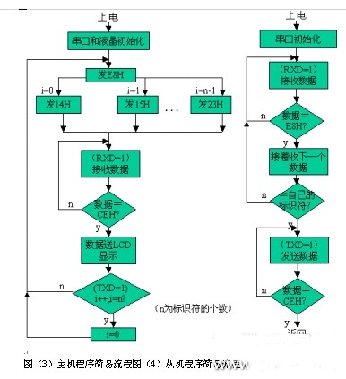
The host queries the slave in a loop-by-point manner. The slave to the name responds and transmits the collected data or signal to the host. The host sends the data to the LCD for display and then enters the next loop. The baud rate of serial communication is 9600, and the data format is defined as 8 data bits plus one stop bit. The serial port initialization procedure is as follows:
Voidinit_usart(void)//serial port initialization
{
UCSRB|=0x18;//Data transmission permission and reception permission
UBRRL=(fosc/16/(baud+1))%256;//Set the baud rate register low byte
UBRRH=(fosc/16/(baud+1))/256;//Set the baud rate register high byte
UCSRC=0x86; / / 8 data bits + 1 stop bit
}
Both the master and the slave receive and send data in a polling manner:
Voidtransmit(unsignedchardata)//data transmission
{
While(!(UCSRA&(1<
UDR=data;//send data
}
Unsignedcharreceive(void)//data reception
{
While(!(UCSRA&(1<
returnUDR; / / receive data
}
5 Conclusion
This paper successfully designed the structure of the vehicle information acquisition system for an electric vehicle. On the one hand, it uses multiple slaves to collect vehicle information to solve the problem that the vehicle information is numerous and difficult to collect. The principle of multi-machine communication with simple serial communication avoids the body. There is a lot of trouble in the surrounding wiring. On the other hand, the liquid crystal display vehicle information is used to provide users with a friendly interface, and at the same time, the vehicle status can be accurately and accurately grasped. From the perspective of the data display and data refreshing effect of the liquid crystal, the in-vehicle information collecting system based on serial communication has a good application prospect.
Antenk manufactures a wide range of application specific board stacking connectors which were designed and built to specific customer requirements. Our experienced staff has developed custom products in a variety of contact styles, pitches and stacking heights. Our designs range from new concepts to duplicating existing market products identically or with improvements. Many desigsn are produced using automated manufacturing processes to increase reliability and provide significant cost savings
Board to Board Connector
Board-to-board (BTB) connectors as the name indicates is used for connecting circuits board together. This kind of connectors are suitable for stacking circuits boards one over another. Flat flexible cables can be avoided using these kinds of connectors; moreover it makes the entire unit more compact. The commonly used BTB connectors are SMT connectors and Berg Strip. We will discuss about them in detail in the following section.
SMT CONNECTOR
Surface Mount Technology (SMT) connector is a commonly found board-to-board connector in advanced circuit boards. As the name indicates this connector is available only in surface mount model. It is carefully mounted on to the solder pads on the surface of the PCB.
SMT connectors are ideal candidate for miniaturization due to their small area of occupancy and stacking height. They are suitable for double layered or multilayered PCBs. They are designed for high performance and reliability.
They commonly found in advanced circuit boards in networking equipment, telephones, mobile phones, computers and other consumer electronics.
Board-to-board (BTB) connectors are used to connect printed circuit boards (PCB), electronic components that contain a conductive pattern printed on the surface of the insulating base in an accurate and repeatable manner. Each terminal on a BTB connector is connected to a PCB. A BTB connector includes housing and a specific number of terminals. The terminal is made from a conductive material (mostly copper alloy), and plated to improve conductivity and antirust. Terminals transmit the current/signal between PCBs connected by BTB; the housing is made of insulating material (mostly plastic).
The basic types of Board to Board Connector
Broadly speaking, Board To Board Connectors are manufactured in the following types:
Pin Header
Elevated Pin Header
Socket
Elevated Socket
Shrouded Header
Box Header

The way mount Board to Board Connectors on a PCB
board to board connectors are available in through hole (TH) and Surface Mount (SMT) variants.
Locating pegs (also referred to as locating posts, alignment pins or board locks) are used to assist alignment of connectors to the PCB. Locating pegs are particularly useful when using surface mount components.

board to board connectors are available in the following pitches: 04mm/0.5mm/0.8mm/1.0mm/1.27mm/2.54mm/3.96mm/4.0mm
For experienced hardware designers choosing board to board connectors is second nature, for the uninitiated it can be daunting. We offer design support and will help guide you through the options available. If you need help with your board to board connector design, contact antenk. Where required antenk also offer non standard pitches.

Board To Board Connectors
0.4mm Board To Board Connectors,0.5mm Female Board To Board Connector,0.8mm 1.0 mmPcb Board To Board Connector,Board To Board Terminal Connectors
ShenZhen Antenk Electronics Co,Ltd , https://www.antenk.com