Mobile charging revolution: achieving small size and best rated power
What is the biggest trouble you have with portable devices? Market research surface: Battery cycle time (ie, the length of time between charges) is an aspect that portable device users are most eager to improve. However, user annoyance does not seem to ease easily, as some of the key design factors involved in the portable device manufacturing process (such as larger screen size, higher screen resolution, and more powerful mobile processors) will only accelerate battery consumption. Speed ​​up and increase the defect of battery cycle time. Recently, portable devices with screen sizes of 4.3 inches and 4.7 inches and a screen resolution of 720p have been introduced, and some screen sizes have even reached 5 inches. These displays require more power than the earlier smaller and lower resolution screens to maintain a satisfactory brightness level on the LCD screen. The table below shows the development of screen resolution in recent years.
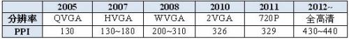
Smartphone screen resolution
Another survey conducted by DisplaySearch also showed that the screen resolution of mobile devices continues to increase. Figure 1 shows that in 2010, the share of mobile devices with pixel densities above 200 ppi was only 22%. By 2015, this share will rise to 50% and will reach 55% further in 2018.
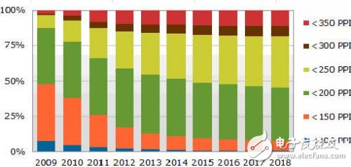
Figure 1: Market share (by screen pixel density)
We can see that the mobile processor is also experiencing the same problem. In a very short time, the processor has transitioned from a single core architecture to a quad core architecture. Although today's CPUs use advanced processing techniques, power consumption continues to increase. Of course, LCD screens and processors are not the only factors that cause increased power consumption. If all possible factors are considered, the battery capacity demand for portable devices will inevitably rise in the trend of chasing "Mobile Everywhere." This seems to be the easiest way for end users to reduce battery cycle time.
Increasing battery capacity seems easy, but it can cause a lot of problems, and the best rated power of the charger is one of the factors to be solved. The USB charger standard has long spurred manufacturers to use the 5 V/1 A power format for smartphone chargers. Since the trend in battery capacity is increasing from the current 1800 mAh to 3500 mAh, it may be higher in the future, so the 5 V/1 A charger is obviously insufficient. When using the current 5 V/1 A format charger to charge a larger battery, the waiting process can be frustrating for the user. In addition, another problem arises while desperately extending the battery cycle time: heat dissipation. The huge design challenge faced by manufacturers is the high temperature problem of high-power chargers. Charging a battery above 2000 mAh with a current of 1 A will generate a high temperature because the charger will remain fully loaded for a longer period of time, and the long-term heat will increase the temperature of the charger case. With the above questions in mind, how can the charger industry break the bottleneck of larger battery capacity?
To fully charge a larger capacity battery in a reasonable amount of time, the easiest way for manufacturers to use is to increase the rated power of the charger. According to the 5 V output of the USB standard, some manufacturers choose to increase the operating current from 1 A to 2 A or 3 A to shorten the charging time; other manufacturers choose to increase the operating voltage to improve efficiency. Although the industry does not seem to have a uniform standard, at least there are still some basic guidelines that apply. To save power, the industry has always had some basic "required" requirements for portable charger designs, such as a highly compact charger size (if designed for mobile devices) and lower standby power consumption. Most importantly, any new, more powerful charger must balance safety and functionality. If all of these requirements are met, we believe that end users will be happy to see a safe and efficient charger, which is a charger that provides sufficient charging capacity and power ratings beyond the current USB charger standard.
Getting the most out of the charging capabilities of the micro-charger is not an easy task, but after years of experience in charger solution development, the industry has some directions to follow.
The key to maintaining a highly compact charger size is the transformer selection. If we want to keep up with the trend of shrinking charger sizes, we need a PWM controller with a higher switching frequency. A relatively high-frequency (eg 85 kHz) PWM controller allows you to choose a smaller transformer (approximately one-third the size of the transformer required to operate at 50 kHz). Currently, PWM controllers operating at 140 kHz are available, allowing manufacturers to further reduce the size of their transformers. Figure 2 below shows the size comparison of the transformer for the 5 W/50 kHz charger (left) and the transformer for the 5 W/85 kHz charger (right).
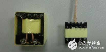
Figure 2: Dimensional differences between transformers operating at 50 kHz (left) and transformers operating at 85 kHz (right).
â— The next design consideration is efficiency. To fully utilize the charging capabilities of the micro-charger, efficiency is clearly a key issue because it directly affects the amount of heat generated. It is quite common for AC-DC conversion to cause a certain amount of power loss. If all losses meet the same ratio, increasing the rated power may even result in more heat loss. This means that if you want to keep a small charger size and you want to double or increase your power rating, the first thing you need to do is to increase efficiency. To increase efficiency, you must understand all the factors that contribute to power loss. Most importantly, the charger size and system efficiency must be balanced. If you only want to reduce the size of the charger and choose a PWM IC with a very high switching frequency, the switching loss will increase dramatically and pose a problem for the designer. If you increase the operating frequency, you will find that it is often difficult to select higher performance components (such as MOSFETs with lower Rds(on) and rectifier diodes with lower forward voltage drop) for the system. Regain efficiency. In short, because size is still important, efficiency is the most critical consideration when you try to increase your power rating. For the PWM IC itself, in order to improve efficiency, some PSR PWM controllers currently operate in Boundary Conduction Mode (BCM) to replace the most commonly used discontinuous conduction mode (DCM) controllers. Using these BCM controllers is one way we should consider.
â— The mobile charger has always implemented a 5 V charging voltage as defined by the USB charger standard. If you want to define a 5 V charger with 2 A or 3 A operating current and facing a higher power rating, the next topic to consider is dynamic response. Currently, most mobile chargers use the 5 V/1 A specification. For chargers of the 5 V/1 A specification, the USB charger standard has clearly defined the voltage drop in order to prevent charging failures caused by sudden leakage currents from zero load to half load or full load. Fundamentally, if the output voltage is maintained at 5 V, the larger the output current, the greater the magnitude of the voltage drop. The reason is that the absolute leakage current (whether between zero load and half load or between zero load and full load) will increase, resulting in an output voltage drop. From this point of view, the traditional PSR PWM may be difficult to implement, and manufacturers can switch to SSR PWM because of the excellent performance.
â— If the charger changes from 5 V/1 A to 5 V/2 A or 5 V/3 A, the power loss on the Usb Cable will only make the voltage drop more severe. If you want to keep the output voltage at 5 V, you need to carefully consider the voltage drop across the cable, and keep in mind that some cables may not be USB certified. Choosing a particular output line with a lower loss level may be a solution. It should also be clear that if the output line is connected to the same 5 V/2 A or 5 V/3 A charger as the 5 V/1 A version, the output voltage drop will increase the charging time. This will slightly offset the benefits of increased rated power.
â— The last consideration is standby power. For a long time, 30 mW of standby power at zero load has been regarded as the standard for mobile chargers. Even when higher power ratings are required, manufacturers must adhere to the 30 mW standard. Although the output power has doubled or even tripled, some manufacturers in the industry want standby power to drop to 10 mW or even close to 0 mW. To design a charger with very low standby power, the most versatile solution is to try to use external circuitry or additional equipment to break the external circuitry or force the IC itself into sleep mode, but these methods also increase the complexity of the design and increase Component count and board size. For charger applications, we recommend a PWM controller with innovative green mode or burst mode control. This helps design a low standby power solution with smaller board size and lower BOM cost.
Now, the power industry will undergo a revolution to meet the needs of portable devices for longer battery cycle times and greater charging capacity. The manufacturer's mission is to take full advantage of the charging capabilities of the micro-charger at a higher level of safety and lower standby power, and this revolution is driven by this challenge.
1. Buy power banks from qualified factory,do not focus on cheap price
only. Batteries, circuit boards have certain fixed costs, higher quality
batteries, the higher purchase cost.
2. Better choose poly-mer
batteries. Polymer batteries output efficiency is relatively stable, but
also has a light weight, safe and efficient.
3. Consider shell beauty at the same time, pay attention to the shell strength and heat resistance.
4. Do not just focus on the conversion rate.
Lithium Polymer Battery Power Bank
Lithium Polymer Power Bank,10000Mah Power Bank,Lithium Polymer Battery Power Bank,4000Mah Power Bank
Custom Usb Gift company limited , https://www.customusbgift.com