Method for measuring power consumption of LCD liquid crystal display module
Method for measuring power consumption of LCD liquid crystal display module
A measurement schematic
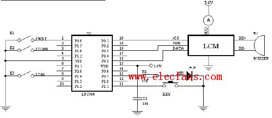
Description K1 K2 K3 is the setting switch of the LCD module. K1 is the WDT. When the switch is closed, the WDT is turned on, otherwise it is turned off.
WDT K2 is TONE, the audio output is turned on when the selection switch is closed; otherwise, K3 is the LCD module oscillator selection switch. When K3 is closed, the external 32.768K crystal is selected; otherwise, the internal RC oscillator is selected. 256K KEY is the confirmation key for the cycle measurement process. Readable indicator When the MCU has set up the LCD module, it will set the IO port P0.1, P0.3, P0.5 of the interface to a high resistance state and then light the LED to indicate the measured value. Read the measurement method. Select LCD by K1 K2 K3 The working mode of the module, then press the KEY key, and observe the LCD when the LED is lit. If the LCD is fully displayed, the current measured by the ammeter at this time is the current that is fully displayed in the currently set working mode. Then press the KEY key
The LCD is all off. At this time, the current measurement value is the current two-source program in power-down mode.
/ ************************************************* **********
DLCD.c
This program is for debugging and parameter measurement of the LCD module of our company's water meter.It can measure the power consumption of the LCD module when it is fully displayed.The power consumption under power-down mode WDT and the power consumption when audio output ... ..
************************************************** ******** /
#include
#define uint unsigned int
/ * Set LCD module interface port parameters for SPI.h * /
sbit CS_PORT = P0 ^ 1; / * CS port * /
sbit CLK_PORT = P0 ^ 3; / * WR port * /
sbit SDA_PORT = P0 ^ 5; / * DATA port * /
#include
/ * Mode selection switch definition * /
sbit K1 = P0 ^ 0; / * WDT open and close selection * /
sbit K2 = P1 ^ 6; / * Audio output on and off selection * /
sbit K3 = P1 ^ 4; / * Internal and external crystal selection * /
sbit KEY = P1 ^ 1; / * 'Confirm' button * /
sbit LED = P0 ^ 7; / * Readable indicator * /
/ * Command word defines that the command word is the lower 8-bit data of 'command mode' * /
#define BIAS 0X52 / * define 1 3 bias 4 back pole * /
#define XTAL32 0X28 / * Use external crystal * /
#define RC256 0X30 / * Use internal 256KRC oscillator * /
#define SYSEN 0X02 / * Turn on the oscillation generator * /
#define LCDON 0X06 / * Turn on the LCD * /
#define SYSDIS 0X00 / * Turn off the oscillation generator * /
#define LCDOFF 0X04 / * Display off * /
#define TONE4 0X80 / * Set BZ output frequency to 4K * /
#define TONEON 0X12 / * Turn on BZ audio output * /
#define TONEOFF 0X10 / * Turn off BZ audio output * /
#define CLRWDT 0X1c / * Clear WDT * /
#define F1 0X40 / * WDT is set to overflow in 4 seconds * /
#define IRQEN 0X10 / * IRQ output prohibited * /
#define IRQDIS 0X00 / * IRQ output enable * /
#define WDTEN 0X0e / * Open WDT * /
#define WDTDIS 0X0a / * Close WDT * /
#define TIMERDIS 0X08 / * Turn off the time base output * /
/ ************************************************* ***********
Delay function function prototype: void Delay ()
Use: Delay for SPI operation
************************************************** ******** /
void Delay ()
{
uchar i;
for (i = 0; i <10; i ++); / * Used to adjust CLK pulse width * /
}
/ ************************************************* ****
Long delay function function prototype: void Delay1s ()
Use: Long delay ...
************************************************** **** /
void Delay1s ()
{
uchar i;
uint j;
for (i = 0; i <10; i ++)
for (j = 0; j <1300; j ++);
}
/ ************************************************* ****
Send command function A type function prototype: void SENDCOMA (uchar com)
Use: When sending the HT1621 command, the ID value must be sent first, and the command word is used to set HT1621.
************************************************** ******* /
void SENDCOMA (uchar com)
{
Start_spi ();
SendBit (0X80,4); / * Send setting command ID = 100 0 * /
SendByte (com); / * Send command word * /
}
/ ************************************************* *****
Send command function B type function prototype: void SENDCOMB (uchar adr)
Use: When sending the HT1621 command, the ID value must be sent first, and then the start address of the data to be written.
Used to write to RAM (you can send data after calling this function) adr is valid for the upper 5 bits
************************************************** ***** /
void SENDCOMB (uchar adr)
{
Start_spi ();
SendBit (0XA0,4); / * Send write display RAM command ID = 101 0 * /
SendBit (adr, 5); / * Specify the write address * /
}
/ ************************************************* *******
Send command function (type C)
Function prototype: void SENDCOMC (uchar com)
Use: Send the ID value first when sending the HT1621 command. Then send the command word of class C
************************************************** ***** /
void SENDCOMC (uchar com)
{
Start_spi ();
SendBit (0X90,4); / * Send command ID = 100 1 * /
SendByte (com); / * Send command word * /
}
/ ************************************************* *******
Fill the display buffer with a prototype: void disp (ucahr dat)
Function: Fill the display buffer to display data in the most convenient form
************************************************** ********* /
void disp (uchar dat)
{
uchar i;
SENDCOMB (0x00); / * Point the data pointer back to 0 and then write the data * /
for (i = 0; i <16; i ++) / * write 16 bytes of data * /
{
SendByte (dat); / * Write data * /
}
}
/ ************************************************* *****
Full display of current measurement optional components WDT audio output internal RC external crystal select time base output off
************************************************** **** /
void DISP_ALL ()
{
/ * The initialization of the display chip is also the wake-up procedure of the LCD module during power-off * /
SENDCOMA (BIAS); / * Set bias voltage, back pole number * /
/ * Select crystal type * /
K3 = 1;
if (K3 == 1) SENDCOMA (RC256); / * Set internal crystal 256K * /
else SENDCOMA (XTAL32);
/ * Start the LCD oscillator * /
SENDCOMA (SYSEN); / * Start oscillator * /
Delay1s ();
SENDCOMA (LCDON); / * Display enable * /
SENDCOMA (TIMERDIS); / * Disable time base output * /
/ * Watchdog selection * /
K1 = 1;
if (K1 == 0)
{
SENDCOMC (F1); / * WDT is set to 4S * /
SENDCOMA (WDTEN); / * Open WDT * /
SENDCOMA (CLRWDT); / * Clear WDT * /
SENDCOMC (IRQEN); / * Open IRQ * /
}
else
{
SENDCOMC (IRQDIS); / * disable IRQ * /
SENDCOMA (WDTDIS); / * Disable WDT overflow flag output * /
}
/ * Audio output selection * /
K2 = 1;
if (K2 == 0)
{
SENDCOMA (TONE4); / * The audio output is set to 4KHz * /
SENDCOMA (TONEON); / * Turn on audio output * /
}
else SENDCOMA (TONEOFF); / * otherwise turn off the audio output * /
disp (0xff); / * Output all display data * /
PT0AD = 0x3e; / * Disable digital input function of SPI interface * /
P0M1 = P0M1 | 0x3e; / * Set SPI port as input only P0M2 corresponding bit is already 0 * /
LED = 1; / * Indicated measurement value can be read * /
KEY = 1; / * wait for the 'confirmation' button * /
while (KEY == 1);
P0M1 = P0M1 & 0xc1; / * Set SPI port as bidirectional port * /
PT0AD = 0x00;
LED = 0; / * Off LED indication * /
while (KEY == 0);
}
/ ************************************************* ********
The power-down measurement part first turns off the audio output and then enters the power-down mode. After power-off, the LCD interface is set to high-impedance state. The IO port should be set to 1 when there is no high-impedance state.
************************************************** ****** /
void DISP_OFF ​​()
{
SENDCOMA (TONEOFF); / * Audio output prohibition * /
Delay1s ();
SENDCOMA (LCDOFF); / * Display disabled * /
Delay1s ();
SENDCOMA (SYSDIS); / * Stop oscillator * /
P0M1 = P0M1 | 0x3e; / * Set SPI port as input only * /
PT0AD = 0x3e; / * Disable digital input function of SPI interface * /
LED = 1; / * Indicates that the measured value of power-down current is readable * /
KEY = 1;
while (KEY == 1);
P0M1 = P0M1 & 0xc1; / * Set SPI port as bidirectional port * /
PT0AD = 0x00;
LED = 0;
while (KEY == 0);
}
/ ************************************************* ***
Main function prototype: void main ()
Function: Query the KEY continuously. If there is a button, perform the full-display measurement status.
************************************************** ******** /
void main ()
{
P0M1 = P0M1 & 0x7f; / * Set LED port as pull-up output * /
P0M2 = P0M2 | 0x80;
while (1)
{
LED = 0; / * Off indicator * /
DISP_ALL (); / * Full display measurement * /
DISP_OFF ​​(); / * Power-off measurement * /
}
}
Header file SPI.h
/ ************************************************* ***************
SPI.h
This header file is some basic functions for reading and writing SPI, which is used to drive and debug LCD modules such as the company's water meters.
************************************************** ********** /
#define uchar unsigned char
extern void Delay (); / * Delay program of device driver * /
/ ************************************************* ************ /
Name: Send data bit prototype: void SendBit (uchar dat, uchar bitcnt)
Purpose: Send bitat data of dat to SPI starting from high bit. (Bitcnt cannot be greater than 8)
/ ************************************************* ************** /
void SendBit (uchar dat, uchar bitcnt)
{
uchar i;
for (i = 0; i
if ((dat & 0X80) == 0)
SDA_PORT = 0;
else
SDA_PORT = 1; / * Send data from high to low * /
Delay ();
CLK_PORT = 1; / * Set the clock line high to inform the controlled device to start receiving digits * /
Delay ();
CLK_PORT = 0; / * Clamp the bus to prepare for the next data bit * /
dat = dat << 1; / * Send data one bit to the left * /
}
}
/ ************************************************* ************
Start spi
Prototype: void Start_spi ()
Role: Start spi for device operation
************************************************** ********** /
void Start_spi ()
{
CS_PORT = 1;
CLK_PORT = 1;
SDA_PORT = 1;
Delay ();
CS_PORT = 0; CS_PORT = 0;
CLK_PORT = 0; CLK_PORT = 0;
}
/ ************************************************* ************** /
Name: Send byte function prototype: void SendByte (uchar dat)
Purpose: send byte data data unit dat to SPI
/ ************************************************* ************** /
void SendByte (uchar dat)
{
SendBit (dat, 8); / * Send byte * /
}
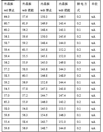
Three measurement data measurement conditions VDD 3.6V, the IO port that is connected to the LCD during measurement is a high-impedance ammeter is Agilent 6 1/2 (LCD module RD and
IRQ pin is floating) P87LPC764 adopts on-chip oscillation 12 clock Internal power-on reset watchdog prohibit reset IO port is high level power-down detection 2.5V
Note The IO CS WR DATA interface with the LCD module should normally be set to the high-impedance state. If the MCU used does not have a high-impedance state, it should be set to a high state. If set to a low level, the LCD module current will increase by about 120uA
(VDD = 3.6V) The power consumption during audio output is very large. The driving current of the buzzer and buzzer should be avoided for a long time and the audio output must be turned off before entering the power down mode. It is sufficient to bias the generator, but it is better to set its working mode again because the current value to be measured is small. VDD on the LCD module interface
Welding with VSS and other points should pay attention to the soldering state and try to prevent the rosin from opening into a leakage circuit part of the water meter LCD module current measurement table in each working mode
LCD Module Data Sheet

18650 And 22650 And 26650 Cells
Lithium Pro Batteries,Tesla Lithium Ion Battery,Lithium Ceramic Battery,Lithium Batteries For Sale
Zhejiang Xinghai Energy Technology Co.,Ltd , https://www.headwayli-battery.com