Clock control level trigger circuit diagram
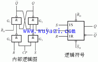
First, we will discuss the high-level triggered RS flip-flop (also known as an RS latch). This type of flip-flop is built by adding two NAND gates to a basic RS trigger. As a result, there are no subscripts like "R" or "S" on the inputs, and the inputs are labeled directly as R and S.
The internal circuit diagram is shown in the figure. Let’s define the state of the trigger before the CP pulse is applied as the initial state, represented by  . After the CP pulse is applied, the new state is referred to as the next state, denoted by
  . The state before the CP pulse is determined by
  and
and  when CP = 0.
If CP = 0, and  is 0, then the output Q is set to 0. Similarly, if
  is 0, the output Q becomes 1. Therefore, the trigger can be set to either “0†or “1†based on these conditions. For the trigger to function normally, both
  and
and  should be high when CP is 0.
Now let's look at the different operating conditions of the RS flip-flop:
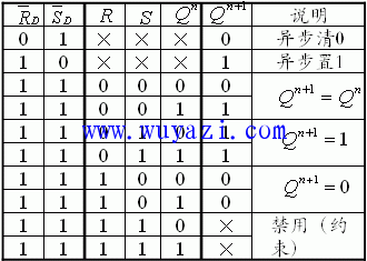
1) When R = 0 and S = 0, after the CP pulse goes high, the state of the trigger remains unchanged:  =
=  .
.
2) When R = 0 and S = 1, after the CP pulse goes high, the output Q becomes 1, which means the trigger is set to “1â€.
3) When R = 1 and S = 0, after the CP pulse goes high, the output Q becomes 0, meaning the trigger is reset to “0â€.
4) When both R and S are 1, the output state becomes unpredictable or random after the CP pulse. During this condition, both  and
and  become 1. This situation should be avoided because it leads to an undefined behavior in the flip-flop.
The truth table for the RS flip-flop clearly shows how the outputs change based on the input values and the CP signal. It serves as a useful reference for understanding the functionality of the device under various conditions.


kolon aramid yarn,strong fiber,high-performance,durable,lightweight
Huizhou Fibercan Industrial Co.Ltd , https://www.fibercan-network.com