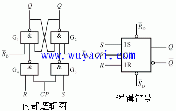
Clock control level trigger circuit diagram
First, we will explore the high-level triggered RS flip-flop, also known as an RS latch. This type of flip-flop is commonly used in digital electronics to store a single bit of data.
The internal circuit of this flip-flop is based on two NAND gates. Unlike the basic RS latch, this version doesn’t have the traditional R and S inputs with subscripts. Instead, it uses a clock pulse (CP) to control when the state changes.
The initial state of the trigger before the CP pulse is applied is represented by  . After the CP pulse is applied, the new state, or secondary state, is shown as
  . The values of
  and
and  are used to determine the initial state when CP=0. If CP=0 and
  = 0, the output Q is set to 0. Similarly, if
  = 0, then Q is set to 1. For the flip-flop to operate normally, both
  and
and  should be high when CP=0.
Now let's look at the different states of the flip-flop based on the input conditions:
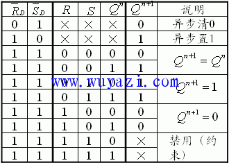
1) When R = 0 and S = 0, the flip-flop remains in its current state after the CP pulse goes high. That is:  =
=  .
.
2) When R = 0 and S = 1, the flip-flop sets the output Q to 1 after the CP pulse is high. This is called the "set" function.
3) When R = 1 and S = 0, the flip-flop resets the output Q to 0 after the CP pulse is high. This is referred to as the "reset" function.
4) When R = 1 and S = 1, the flip-flop enters an undefined or random state. While CP is high, both outputs may become 1, which is considered an invalid condition and should be avoided in practical applications.
The truth table for the RS flip-flop clearly illustrates these behaviors. It shows how the output Q changes based on the inputs R, S, and the clock signal CP.


Fiber Optic Loopback,Fiber Loopback,Fiber Loopback Plug,Fibre Optic Loopback Connector
Huizhou Fibercan Industrial Co.Ltd , https://www.fibercan-network.com