Improve the measurement speed of the WLAN test system
As the industry continues to seek lower test costs, many RF test engineers must continue to reduce measurement time. As you know, the testing of wireless network (WLAN) devices must also cater to this trend. Whether it is an automated test system for design verification or a test operation for the final product, the measurement speed of the test system has become increasingly important. However, in most cases, in addition to reducing test time and reducing test costs, the measurement accuracy and repeatability of the system cannot be affected. This technical article will address the WLAN measurement operations and illustrate several trade-offs that may affect the measurement speed. After understanding the concepts, a better practice description will be provided for the measurement speed of the test system. This technical article will explain the following elements in order: average and repeatability; EVM of complete pulse and partial pulse; composite measurement and single measurement; measurement frequency span and measurement time, and finally the relationship between CPU and measurement time. For the above related elements, this technical article will perform sample measurement operations using the NI PXIe-5663 - 6.6 GHz RF vector signal analyzer. These examples use the NI PXIe-5673 - 6.6 GHz RF vector signal generator as an excitation. And all of the examples use the NI WLAN Measurement Suite, which includes NI LabVIEW and LabWindowsTM/CVI signal generation and analysis toolkits to build measurement platforms. To learn more about how to set up a PXI WLAN test system, see Configuring a Software-Defined WLAN Test System. Although this technical article focuses on the operation of PXI RF instruments, the same basic measurement elements may be common to any RF instrument. Therefore, both PXI instruments and traditional RF instruments can be used to improve the performance.

1. Weighing Factors 1 – Average and Repeatability Whether it is an application for automated design inspection or production testing, a common technique for improving the repeatability of measurement results is the result of average multiple measurements. However, if a large number of average values ​​are to be set to improve the repeatability of the measurement results, the measurement time will be increased. In general, the overall measurement time can be linearly adjusted by the number of average values. Therefore, if a single measurement operation takes 20ms, then the same measurement will take nearly 200ms when it is averaged 10 times.
Furthermore, since the averaging operation can offset the non-repeatable impairments, such as AddiTIve white Gaussian noise (AWGN), between multiple measurements, the repeatability can be effectively improved. To understand the impact of average operation on repeatability, you can use the NI PXIe-5673 RF vector signal generator with the NI PXIe-5663 RF vector signal analyzer to perform loopback testing. With the above device, an 802.11g Orthogonal Frequency Division Multiplexing (OFDM), -10 dBm power intensity RF signal can be generated at 2.412 GHz. Similarly, using four different signal types – BPSK (6 Mbps), QPSK (18 Mbps), 16-QAM (24 Mbps), and 64-QAM (54 Mbps), you can understand the pulse size and modulation type versus measurement time. Impact. If a 1024-bit payload is used, then each signal type will have a different number of OFDM symbols. For example, a BPSK pulse will have 343 symbols and a 64-QAM pulse will use 39 symbols. Therefore, the pulse interval of each signal type is also different, and Table 1 shows the difference in pulse widths of different types.
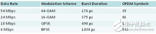
Table 1 Modulation method of 802.11a/g variable data transmission rate, pulse interval and number of symbols
Error vector strength (EVM) measurement operations can provide complete signal modulation quality. In the EVM measurement operation, there are two built-in methods that can show average results. For IEEE 802.11a/g pulses, the results of the measurements will cover the individual OFDM subcarriers and symbols. Expressed in the root mean square (RMS) of the EVM. From Table 1, it should be possible to see directly the number of symbols in the pulse, and if the EVM is a lower 6 Mbps (BPSK) data rate, it should be possible to generate repeatable measurement operations with more than 54 Mbps pulses. It can thus be seen that longer pulses also have more symbols. However, the above hypothesis is true only when the EVM is represented as RMS by a complete pulse (rather than a specific partial pulse). The trade-off element 2 will analyze the partial pulses to illustrate the relevant repeatability.
In the general case, we can assume that more repeatable EVM results will be produced when performing longer pulse measurements. Figure 1 shows the relationship between the average number of times and the standard deviation of the measurement. These measurements were performed using the NI PXIe-5673 RF vector signal generator and the NI PXIe-5663 RF vector signal analyzer. An average RF power of -10 dBm was used, and the intermediate frequencies of both instruments were set to 2.412 GHz.
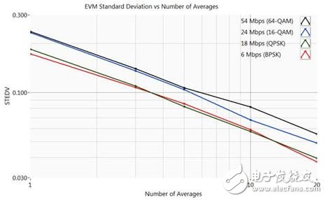
Figure 1 Average operation reduces the standard deviation of the measured mean
Figure 1 shows that as the average number of uses per measurement operation increases, the standard deviation of 1000 EVM measurements will decrease. Please note that since the signal source used in Figure 1 is an RF vector signal generator - specifically designed to produce repeatable signals, the EVM and standard deviation in Figure 1 are significantly better than those produced by 802.11g converters. The actual situation. Therefore, the results shown in Figure 1 can be used as a criterion for repeatability. Also, please note that it is only meaningful to measure the repeatability of the measurement in terms of Absolute measurement value. In general, as long as the EVM standard of the test instrument is higher, the effect of repeatability is smaller. Table 2 shows the EVM results when the measurement operation is set to 10 times average.
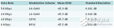
Table 2 EVM and modulation type remain relatively consistent
Table 2 shows that the EVM will be consistent regardless of the modulation method. However, this also means that the user can obtain a better standard deviation by a longer pulse. Of course, you will also need to measure more symbols. For example, if 10 averaging is performed to achieve a standard deviation of 0.081 dB on the 64-QAM signal, then when measuring the complete pulse of the BPSK signal, the same standard deviation can be achieved with only 5 averaging.
In general, it takes only a long measurement time to achieve a lower standard deviation result by averaging. Table 3 illustrates this relationship with a 54 Mbps pulse. Note that the measurement times in Table 3 include gated power and EVM measurement operations.
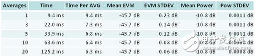
Table 3. Measurement time increases as the average number of times increases
In Table 3, we performed a composite EVM and gated power measurement operation using a PXIe-5663 RF vector signal analyzer with a set of NI PXIe-8106 controllers. The EVM is calculated from the RMS of the complete pulse; and the mean and standard deviation are calculated over more than 1000 measurement operations. Table 3 shows the linear relationship between the measurement time and the average number of times. The NI WLAN Analysis Toolkit uses the so-called Asynchronous fetching technique, which handles the previous records as the analyzer extracts new records. Therefore, the user can perform measurement operations on multiple averaging without being limited by the linear time (Linear TIme). In addition, please note that the single-average EVM and power measurement listed in Table 3 will take 9.4ms, but if the average number of times is set to 10, the measurement operation will only take 63.6ms, which is the average consumption per time. The time is 6.3ms.
2. Tradeoff Element 2 – Complete Pulse EVM and Partial Pulse EVM
Faster EVM measurements can be obtained in some cases if the instrument is set to perform partial pulse EVM instead of processing full pulse EVM measurements. Processed by default, the NI WLAN Analysis Toolkit will perform OFDM EVM measurements as the RMS for each symbol in all subcarriers in the entire pulse train. Similarly, the NI WLAN Analysis Toolkit uses 802.11b DSSS EVM measurements as the RMS for all segments of the entire pulse sequence. However, there are still many examples showing that if only the first part of the pulse is measured, not only can reproducible measurements be obtained and measurement time saved. In this case, you can programmatically configure the number of symbols or the number of segments required to operate the EVM.
To illustrate the impact of partial pulse analysis, we can use two different sets of pulses and set them to use BPSK (6 Mbps) and 64-QAM (54 Mbps), respectively. As shown in Table 1, the BPSK pulse has a length of 1434 μs and 343 sets of symbols; and the 64-QAM pulse has a length of 176 μs and 39 sets of OFDM symbols. Similarly, this experiment shows the results of computing the EVM measurement time as an average of 1000 measurements. Each measurement is achieved by averaging and closing the trajectory. Figure 2 shows the relationship between the number of symbols used to perform the arithmetic operation and the BPSK pulse measurement time.
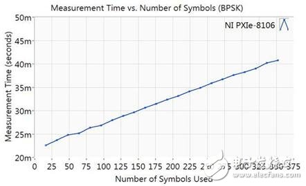
Figure 2 Relationship between standard deviation and sign measured by BPSK pulse
As shown in Fig. 2, for a longer pulse sequence such as BPSK, if only a part of the sequence can be analyzed instead of all symbols, the measurement time can be greatly shortened. If you use fewer symbols, you can reduce the measurement time of this pulse from 40ms to 22ms. In addition, there may be slight deviations in the repeatability of the measurement results under faster measurement conditions.
Obviously, the advantage of partial pulse measurement is that it can shorten the measurement time of longer pulses. The reason for this result is that for longer pulse trains, the preparation time for a measurement (memory allocation, drive call, and data acquisition time) is only a small fraction of the total pulse measurement time. In contrast, for shorter pulse sequences (such as 64-QAM and 16QAM), the flexibility is relatively small compared to the symbols used. For example, a 64-QAM pulse sequence includes only 39 leading symbols. Because you need more than 16 symbols for repeatable EVM measurements, you will not be able to significantly reduce measurement time on 64-QAM pulse sequences. Figure 3 shows the relationship between the measurement time and the number of symbols for a pulse of 54 Mb/s.
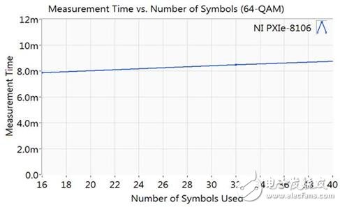
Figure 3 Partial pulse analysis will be faster for longer pulse trains
The NI PXIe-8106 controller was used to speed up the measurement. Please note that these results only apply to certain conditions. For longer BPSK and QPSK 802.11a/g signals, only partial pulse analysis can shorten the measurement time.
With the WLAN Analysis Toolkit, the same method can be used to set the IEEE802.11b EVM measurement operation to calculate only part of the pulse. Since 802.11b uses Direct Sequence Spread Spectrum (DSSS), the EVM will be calculated by multi-level segments. Since the default EVM measurement will calculate the complete pulse, the user can set the WLAN Analysis Toolkit to perform EVM measurement operations on only 1000 segments.
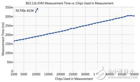
Figure 4. 802.11b measurement time with EVM configured with fewer DSSS fragments
As can be seen from Fig. 4, if the number of segments to be measured is reduced for a signal pulse of 1 Mbps, the measurement time can be shortened from 300 ms to 170 ms.
Flexible in order quantity:
Samples can be provided before mass production, and MOQ can be discussed accordingly.
Carbide Reamers are used to drill a hole in material with a pilot hole. It is especially suitable for machining the forming hole with very strict terms of surface roughness, roundness, cylindricity, concentricity, burr free and other quality requirements.
OPT present to our clients a wide variety of carbide reamers, according to the flute type it can be classifed to Straight Fluted Reamers, Right Hand Fluted Reamers and Left Hand Fluted Reamers
Advantage:
Unique guidepad geometry allows for excellent roundness and straightness, even in an interrupted cut condition.
Surface roughness is reduced obviously.
Features
With 4, 6 or 8 flute
Multi-diameter tool allowing for excellent hole size and concentricity between diameters.
PRODUCT DETAIL:


PRODUCTING PROGRESS:

PAYMENT AND DELIVERY:

PRODUCT EQUIPMENT :
+
ABOUT US :
We are specialize in manufacturing PCD diamond tools and Carbide tools. Our major product inclulde PCD Inserts , PCD Reamers , PCD End Mills, PCD Taps, Cabide Inserts,Carbide Drills, Carbide Reams, Taps etc.,
We also offered customized cutting tools per drawings, and provide package according to customer requirements. We manufacture a series range of cutting tools for machining of Cast iron, Aluminium alloy and Non-Ferros metal, it is widely used in all major sectors like Automobiles, Engineering, Aerospace, Aviation and 3C industry. Premium quality of raw material is used in the production and strict examination during processing with advanced equipment, so our client are satisfied with our reliable quality and on-time delivery.
Our best selling of cutting tools include PCD Inserts, PCD End Mill, PCD Ball Nose Mill, PCD Reamer, Carbide Taps , Carbide End Mill, Special Form Cutter and many more. For these years we have been made a large forward in the technologies of manufacturing cutting tools. With high quality on performance and price, our product sells well both on domestic and overseas market. And we will always focus on the quality and best service, to make long business relationship.

quanlity control:
We have dedicated team of quality control and precise equipment to keep good and stable performance for our products and processing services.

Ceramic Cutters
OPT Cutting Tools Co., Ltd. , https://www.optdiamondtoolss.com