Detailed analysis of the principle of lithium battery protection board
The reason why lithium batteries (fillable) need protection is determined by its own characteristics. Because the material of the lithium battery itself determines that it can not be overcharged, overdischarged, overcurrent, short circuited and ultra-high temperature charge and discharge, the lithium battery lithium battery assembly will always follow an exquisite protection board and a current fuse.
Lithium battery protectionThe protection function of the lithium battery is usually completed by the protection circuit board and the current device such as the PTC. The protection board is composed of electronic circuits, and the voltage of the battery core and the charging and discharging circuit are accurately monitored at -40 ° C to +85 ° C environment. Current, timely control of the current circuit on and off; PTC in the high temperature environment to prevent battery damage.
Ordinary lithium battery protection boards usually include control ICs, MOS switches, resistors, capacitors, and auxiliary devices FUSE, PTC, NTC, ID, memory, and so on. The control IC controls the MOS switch to be turned on under all normal conditions, so that the cell and the external circuit are turned on, and when the cell voltage or the loop current exceeds a prescribed value, it immediately controls the MOS switch to turn off, and protects the cell. Safety.
When the protection board is normal, Vdd is high level, Vss, VM is low level, DO and CO are high level. When any parameter of Vdd, Vss, VM is changed, the level of DO or CO will be A change has occurred.
Lithium battery protection board principleThe reason why lithium batteries (fillable) need protection is determined by its own characteristics. Because the material of the lithium battery itself determines that it can not be overcharged, overdischarged, overcurrent, short circuited and ultra-high temperature charge and discharge, the lithium battery lithium battery assembly will always follow an exquisite protection board and a current fuse.
The protection function of the lithium battery is usually completed by the protection circuit board and the current device such as the PTC. The protection board is composed of electronic circuits, and the voltage of the battery core and the charging and discharging circuit are accurately monitored at -40 ° C to +85 ° C environment. Current, timely control of the current circuit on and off; PTC in the high temperature environment to prevent battery damage.
Ordinary lithium battery protection boards usually include control ICs, MOS switches, resistors, capacitors, and auxiliary devices FUSE, PTC, NTC, ID, memory, and so on. The control IC controls the MOS switch to be turned on under all normal conditions, so that the cell and the external circuit are turned on, and when the cell voltage or the loop current exceeds a prescribed value, it immediately controls the MOS switch to turn off, and protects the cell. Safety.
When the protection board is normal, Vdd is high level, Vss, VM is low level, DO and CO are high level. When any parameter of Vdd, Vss, VM is changed, the level of DO or CO will be A change has occurred.
1. Overcharge detection voltage: In the normal state, Vdd gradually rises to the voltage between VDD and VSS when the CO terminal changes from a high level to a low level.
2. Overcharge release voltage: In the state of charge, Vdd gradually decreases to the voltage between VDD and VSS when the CO terminal changes from low level to high level.
3. Overdischarge detection voltage: In the normal state, Vdd gradually decreases to the voltage between VDD and VSS when the DO terminal changes from high level to low level.
4. Overdischarge release voltage: In the overdischarge state, Vdd gradually rises to the voltage between VDD and VSS when the DO terminal changes from low level to high level.
5. Overcurrent 1 detection voltage: In the normal state, the VM gradually rises to the voltage between VM and VSS when DO changes from high level to low level.
6. Overcurrent 2 detection voltage: In the normal state, the VM rises from OV at a speed of 1 ms or more and 4 ms or less to the voltage between VM and VSS when the DO terminal changes from a high level to a low level.
7. Load short-circuit detection voltage: In the normal state, the VM rises at a speed of 1 μS or more and 50 μS or less from OV to the voltage between VM and VSS when the DO terminal changes from a high level to a low level.
8. Charger detection voltage: In the overdischarge state, the VM gradually drops to OV and the VM-VSS voltage changes from low level to high level.
9. Current consumption during normal operation: In the normal state, the current flowing through the VDD terminal (IDD) is the current consumption during normal operation.
10. Over-discharge current consumption: In the discharge state, the current flowing through the VDD terminal (IDD) is the over-current discharge current consumption.
Typical lithium battery protection circuitDue to the chemical characteristics of lithium batteries, during normal use, the internal chemical reaction of electrical energy and chemical energy is mutually converted, but under certain conditions, such as overcharging, overdischarging and overcurrent, the internal battery will be caused. Chemical side reactions occur, which will seriously affect the performance and service life of the battery, and may generate a large amount of gas, causing the internal pressure of the battery to rapidly increase and explode, resulting in safety problems. Therefore, all lithium batteries require a protection. The circuit is used for effectively monitoring the charging and discharging states of the battery, and shutting down the charging and discharging circuits under certain conditions to prevent damage to the battery.
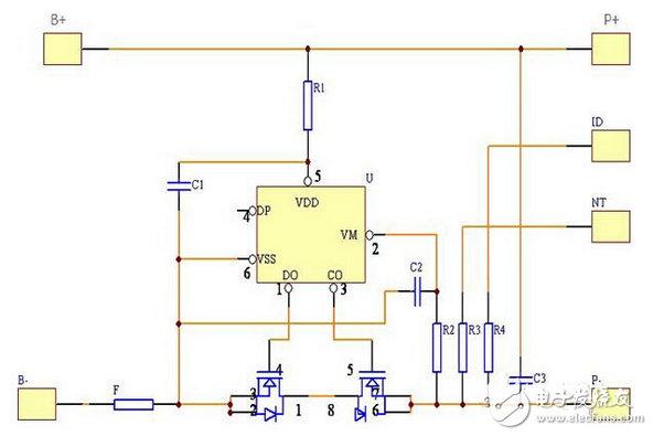
The figure below shows a typical lithium battery protection circuit schematic.
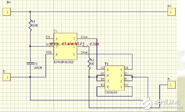
As shown in the figure above, the protection loop consists of two MOSFETs (V1, V2) and a control IC (N1) plus some RC components. The control IC is responsible for monitoring the battery voltage and the loop current, and controlling the gates of the two MOSFETs. The MOSFET acts as a switch in the circuit, respectively controlling the conduction and shutdown of the charging circuit and the discharging circuit, and C3 is a delay capacitor. With overcharge protection, over-discharge protection, over-current protection and short-circuit protection, its working principle is as follows:
1, normal stateIn the normal state, the "CO" and "DO" pins of N1 output high voltage in the circuit, both MOSFETs are in conduction state, and the battery can be freely charged and discharged. Since the on-resistance of the MOSFET is small, it is usually smaller than 30 milliohms, so its on-resistance has little effect on the performance of the circuit. The current consumption of the protection circuit in this state is μA level, usually less than 7μA.
2, overcharge protectionLithium-ion batteries require a constant current/constant voltage. In the initial stage of charging, they are charged at a constant current. As the charging process, the voltage rises to 4.2V (depending on the cathode material, some batteries require a constant voltage of 4). .1V), turn to constant voltage charging until the current is getting smaller and smaller. When the battery is being charged, if the charger circuit loses control, the battery voltage will exceed 4.2V and continue constant current charging. At this time, the battery voltage will continue to rise. When the battery voltage is charged to over 4.3V, the battery The chemical side reactions will increase, causing battery damage or safety problems. In a battery with a protection circuit, when the control IC detects that the battery voltage reaches 4.28V (this value is determined by the control IC and different ICs have different values), its "CO" pin will change from high voltage to zero voltage. V2 is turned from on to off, thus cutting off the charging circuit, so that the charger can no longer charge the battery, which acts as an overcharge protection. At this time, due to the presence of the body diode VD2 that is provided by the V2, the battery can discharge the external load through the diode. There is still a delay time between when the control IC detects that the battery voltage exceeds 4.28V and when the V2 signal is turned off. The length of the delay time is determined by C3, usually set to about 1 second, to avoid interference. Misjudgment.
3, short circuit protectionWhen the battery is discharging to the load, if the loop current is so large that U>0.9V (this value is determined by the control IC and different ICs have different values), the control IC determines that the load is short-circuited, and its “DO†pin It will quickly change from a high voltage to a zero voltage, turning V1 from on to off, thus cutting off the discharge loop and providing short-circuit protection. The short-circuit protection has a very short delay time, usually less than 7 microseconds. Its working principle is similar to overcurrent protection, except that the judgment method is different, and the protection delay time is also different. In addition to the control IC, there is another important component in the circuit, the MOSFET, which acts as a switch in the circuit. Since it is directly connected between the battery and the external load, its on-resistance has a performance on the battery. The effect is that when the selected MOSFET is better, its on-resistance is small, the internal resistance of the battery pack is small, and the load carrying capacity is also strong, and the power consumed during discharge is also small.
4, over current protectionDue to the chemical characteristics of lithium-ion batteries, battery manufacturers stipulate that their discharge current should not exceed 2C (C=battery capacity/hour). When the battery exceeds 2C current discharge, it will cause permanent damage or safety problems. During the normal discharge of the battery, the discharge current is passed through two MOSFETs in series. Due to the on-resistance of the MOSFET, a voltage is generated across the MOSFET. The voltage value U=I*RDS*2, RDS is a single MOSFET on-resistance, the “V-†pin on the control IC detects the voltage value. If the load is abnormal due to some reason, the loop current increases, and the loop current is so large that U>0.1V (this value) When the control IC determines that different ICs have different values, the "DO" pin will be converted from a high voltage to a zero voltage, turning V1 from on to off, thereby cutting off the discharge loop and making the current in the loop zero. It acts as an overcurrent protection. There is also a delay between when the control IC detects an overcurrent and when the V1 signal is turned off. The length of the delay is determined by C3, usually about 13 milliseconds, to avoid misjudgment caused by interference. In the above control process, the overcurrent detection value depends not only on the control value of the control IC, but also on the on-resistance of the MOSFET. When the MOSFET on-resistance is larger, the over-current protection is applied to the same control IC. The smaller the value.
5, over discharge protectionWhen the battery is discharged to the external load, its voltage will gradually decrease with the discharge process. When the battery voltage drops to 2.5V, its capacity has been completely discharged. At this time, if the battery continues to discharge the load, it will cause the battery. Permanent damage. During the battery discharge, when the control IC detects that the battery voltage is lower than 2.3V (this value is determined by the control IC, different ICs have different values), its "DO" pin will be converted from a high voltage to a zero voltage, so that V1 turns from on to off, which cuts off the discharge circuit, so that the battery can no longer discharge the load and protects the discharge. At this time, due to the presence of the V1 body diode VD1, the charger can charge the battery through the diode. Since the battery voltage can no longer be lowered under the over-discharge protection state, the current consumption of the protection circuit is required to be extremely small. At this time, the control IC will enter a low-power state, and the entire protection circuit consumes less than 0.1 μA. There is also a delay time between when the control IC detects that the battery voltage is lower than 2.3V and when the V1 signal is turned off. The length of the delay time is determined by C3, usually set to about 100 milliseconds to avoid interference. Misjudgment
SHAOXING COLORBEE PLASTIC CO.,LTD , https://www.colorbeephoto.com