Siemens PLC S7-200 common 71 fault summary and solution
The programmable logic controller produced by Siemens (SIEMENS) in Germany is also widely used in China and has applications in fields such as metallurgy, chemical engineering and printing production lines. Siemens (SIEMENS) PLC products include LOGO, S7-200, S7-1200, S7-300, and S7-400. Siemens S7 series PLCs are small, fast, and standardized. They have network communication capabilities, stronger functions, and high reliability. S7 series PLC products can be divided into micro-PLC (such as S7-200), small-scale performance requirements of the PLC (such as S7-300) and high-performance requirements of the PLC (such as S7-400) and so on.
Siemens SIMATIC series PLC, was born in 1958, experienced C3, S3, S5, S7 series, has become a widely used programmable controller.
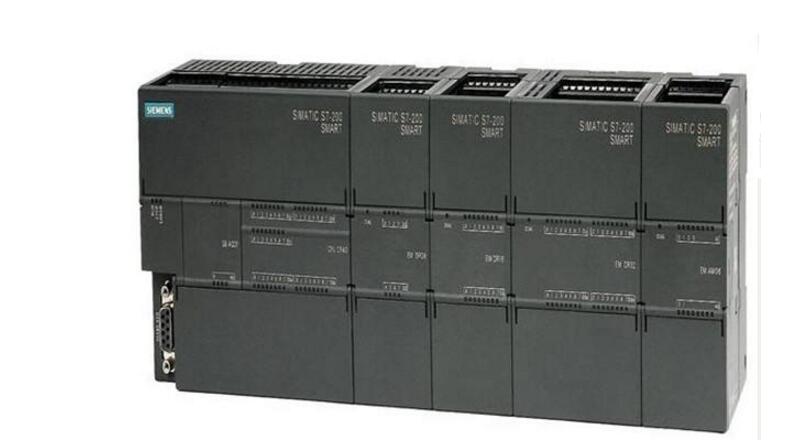
The basic hardware components of Siemens PLC S7-200 series PLCThe application area of ​​SIMATIC S7-200 has been extended from replacing relays and contactors to more complex automation tasks in stand-alone, network and distributed configurations. The S7-200 is also increasingly providing access to areas where special electronic equipment was previously developed for economic reasons.
The S7-200 series PLCs are available in 4 different basic units and 6 models of expansion units. The system consists of a basic unit, an expansion unit, a programmer, a memory card, a writer, a text display, and the like.
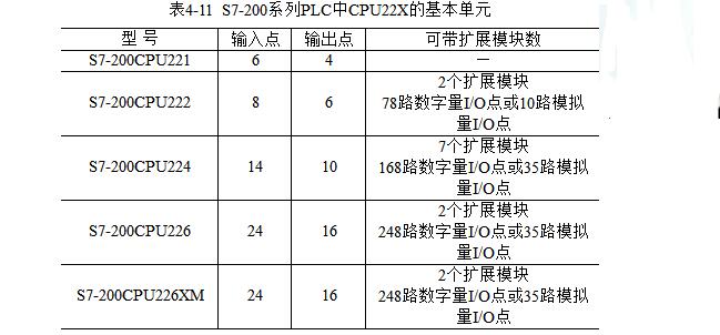
1. Basic unitThe S7-200 series PLC can provide 4 different basic models of 8 kinds of CPUs for selection and use. The distribution of input and output points is shown in Table 4-11:
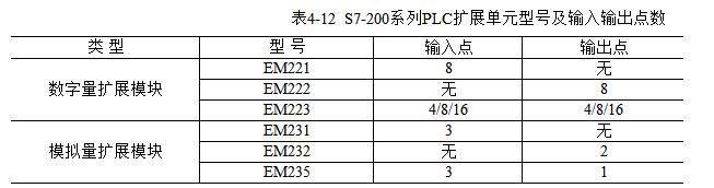
S7-200 series PLC mainly has 6 types of expansion units, which itself has no CPU, and can only be used in connection with the basic unit. It is used to expand the number of I/O points. The S7-200 series PLC expansion unit models and the distribution of input and output points are listed. 4-12 shows.
When the PLC is officially running, no programmer is required. The programmer is mainly used to compile, store and manage user programs, and send user programs to the PLC. During the debugging process, monitoring and fault detection are performed. S7-200 series PLC can use a variety of programmers, generally can be divided into simple and intelligent.
The simple programmer is compact, simple and practical, and inexpensive. It is a very good on-site programming and monitoring tool, but its display function is poor. It can only be input by the instruction table, and it is not convenient to use. The intelligent programmer uses a computer to perform programming operations. The dedicated programming software is loaded into the computer. The ladder diagram language can be directly programmed to realize on-line monitoring. It is very intuitive and powerful. The dedicated programming software for the S7-200 series PLC is STEP7. -Micro/WIN.
4. Program memory cardIn order to ensure the safety of the program and important parameters, the small PLC is generally equipped with an external EEPROM cartridge interface. Through this interface, the contents of the cartridge can be written to the PLC, and the programs and important parameters in the PLC can be transferred to the external EEPROM cartridge. As a backup. The program memory card EEPROM has two kinds of 6ES 7291-8GC00-0XA0 and 6ES 7291-8GD00-0XA0, and the program capacity is 8K and 16K respectively.
5. WriterThe function of the writer is to realize the program transfer between the PLC and the EPROM. The program in the RAM area in the PLC is solidified to the program memory card through the writer, or the program in the program memory card in the PLC is transmitted through the writer. Go to RAM area.
6. Text displayThe text display TD200 is not only a display device for displaying system information, but also can be used as a control unit to modify a certain amount of values ​​or directly set the input/output amount. The display of text information can display up to 80 messages with the selection/confirmation method, and the status of each message can be up to 4 variables. Process parameters can be displayed on the display and can be modified at any time. Each of the 8 programmable function keys on the TD200 panel is assigned a memory bit. These function keys enable parameter setting and diagnosis when the system is started up and tested.
1. Strong performance, optimal modularity and open communication
2, compact and compact - ideal for any application in a narrow space
3, basic and advanced features in all CPU models
4, large-capacity program and data storage
5. Outstanding real-time response - Full control of the entire process at all times improves quality, efficiency and safety
6. Easy to use STEP 7-Micro/WIN engineering software - ideal for beginners and experts
7, integrated RS 485 interface or as a system bus
8, extremely fast and precise operation sequence and process control
9, through the time to interrupt the complete control of the time-critical process
1. What environment does Siemens Step7Micro/WINV4.0 install to work properly?
Step7Micro/WINV4.0 installation and operating environment:
WINOOWs2000SP3 and above
WINOOWsXPHome
WINOOWsXPProfessional
Siemens plc is not tested under other operating systems and is not guaranteed to work.
2. How is Step7Micro/WINV4.0 compatible with other versions?
Project files generated by Micro/WINV4.0. Old versions of Micro/WIN cannot be opened or uploaded.
What is the difference between 3, siemens200PLC hardware version?
The second generation S7-200 (CPU22x) series is also divided into several major hardware versions.
The 6ES721x-xxx21-xxxx is the 21st edition; the 6ES721x-xxx22-xxxx is the 22nd edition.
Compared with version 21, version 22 has improved hardware and software. The 22 version is downwardly compatible with the 21 version feature.
The main difference between 22 and 21 is:
The free port communication rate of the 21st edition CPU 300, 600 is replaced by 22 edition 57600, 115200, the 22 edition no longer supports 300 and 600 baud rate, the 22 edition no longer has the restriction of the intellectual module position
4, Siemens plc power to how to connect?
In the power supply wiring to the CPU, we must be very careful to distinguish what kind of power supply, if the 220VAC is connected to the 24VDC power supply CPU, or accidentally received 24VDC sensor output power, will cause the CPU to damage.
5: How many bits is the S7-200PLC processor?
The central processing chip of the S7-200 CPU has a 32-bit data length. The data length of the CPU accumulator AC0/AC1/AC2/AC3 can also be seen.
6. How to perform the power requirement and calculation of S7-200?
The S7-200 CPU module provides 5VDC and 24VDC power supplies:
When there is an expansion module, the CPU provides 5V power through the I/O bus. The sum of the 5V power consumption of all expansion modules cannot exceed the power rating provided by the CPU. If not enough can not use external 5V power supply.
Each CPU has a 24VDC sensor power supply that provides 24VDC for the local input point and expansion module input points and expansion module relay coils. If the power requirement exceeds the power rating of the CPU module, you can add an external 24VDC power supply to the expansion module.
The so-called power supply calculation is to use the power supply capacity that the CPU can provide, minus the power consumption required by each module.
note:
The EM277 module itself does not require a 24VDC power supply. This power supply is dedicated to the communication port. The 24VDC power requirement depends on the load on the communication port.
The communication port on the CPU can connect the PC/PPI cable and the TD200 and supply them with power. This power consumption is no longer included in the calculation.
7. Can 200 PLC work at minus 20 degrees?
The working environment requirements of the S7-200 are:
0°C-55°C, horizontal installation
0°C-45°C, vertical installation
Relative humidity 95%, no condensation
Siemens also offers the S7-200 wide temperature range product (SIPLUSS7-200):
Operating temperature range: -25°C-+70°C
Relative humidity: 98% at 55°C, 45% at 70°C
Other parameters are the same as those of ordinary S7-200 products
S7-200 wide temperature products, each with its own order number, can be found on the SIPLUS product homepage. If not found, there is no corresponding SIPLUS product.
Text and graphics display panels do not have a wide temperature type product.
Also note that there is no spot in the country. Please contact your local Siemens office or distributor if you need to.
8. How fast is the digital input/output (DI/DO) response speed? Can I make high-speed input and output?
The S7-200 has a hardware circuit (chip, etc.) on the CPU unit to handle high-speed digital I/O, such as high-speed counter (input), high-speed pulse output. These hardware circuits work under the control of the user program and can reach very high frequencies; however, the number of points is limited by hardware resources.
The S7-200CPU works according to the following mechanism:
Read input point status to input image area
Execute the user program, perform logical operation, and get the new state of the output signal
Write output signal to output image area
Note: As long as the CPU is in the running state, the above steps are carried out on a weekly basis. In the second step, the CPU also performs communications, self-checks, and other tasks.
The above three steps are the software processing of the S7-200 CPU and can be considered as the program scan time. In fact, the S7-200's speed of digital processing is limited by the following factors:
Input hardware delay (from the moment the state of the input signal changes, to when the CPU refreshes the input image area)
CPU internal processing time, including:
Read input point status to input image area
Execute the user program, perform logical operation, and get the new state of the output signal
Write output signal to output image area
Output hardware delay (the time from the output buffer status change to the actual level change at the output point)
The above three periods A, B, and C are the main factors that limit Siemens PLC's ability to handle the digital response speed.
A practical system may also need to consider the input and output device delays, such as the output point external relay operating time.
The above data are all indicated in the "S7-200 System Manual". Here is a list comparison. The time delay (filter) time of some input points on the CPU can be set in the "system block" of the programming software Micro/WIN. The default filter time is 6.4ms.
If the vulnerable signal is connected to the DI point on the CPU that can change the filter time, adjusting the filter time may improve the signal detection quality.
Input points that support the high-speed counter function are not constrained by this filter time when the corresponding function is turned on. The filter setting is also effective for refreshing the input image area, digital input interruption, and pulse catching functions.
Some output points are faster than others because they can be used for high-speed output functions and have special design in hardware. When the hardware high-speed output function is not used exclusively, they are treated just like ordinary points.
The relay output switching frequency is 1Hz.
9. What are the countermeasures for the S7-200 to handle fast response signals?
Using the CPU's built-in high-speed counter and high-speed pulse generator to process sequential pulse signals
Hardware interrupts using some of the CPU's digital input points are handled in the interrupt service routine; the delay into the interrupt can be ignored.
The S7-200 has direct read input and direct write output instructions that can override the time limit of the program scan cycle
Capture a short pulse using the "Pulse capture" function of the partial CPU digital input
Note: The minimum periodic timing task in the S7-200 system is 1ms.
All measures to achieve rapid signal processing must consider the impact of all limiting factors. For example, it is obviously unreasonable to choose a hardware with a 500μs output delay for a signal that requires a millisecond response speed.
10, S7-200 program scanning time and program size related?
The program scan time is proportional to the size of the user program.
The "S7-200 System Manual" has data on the execution time of each instruction. It is actually difficult to pre-calculate the program scan time in advance, especially if the program has not yet been programmed.
It can be seen that the conventional PLC processing mode is not suitable for digital signals requiring high time response. It may be necessary to use special methods depending on the specific task.
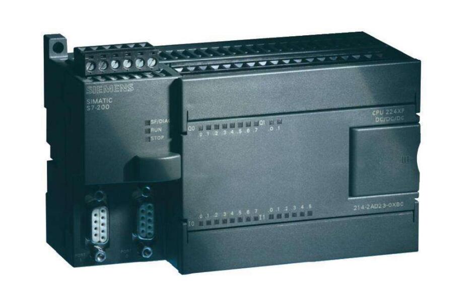
11, CPU224XP high-speed pulse output can reach the fastest?
The CPU224XP's high-speed pulse outputs Q0.0 and Q0.1 support frequencies up to 100KHz.
Q0.0 and Q0.1 support 5-24VDC output. But they must be grouped together with Q0.2-Q0.4 to output the same voltage. High-speed output can only be used in CPU224XPDC/DC/DC models
12. Is the analog input on the CPU224XP a high-speed response?
Its response speed is 250ms, which is different from the data of the analog expansion module. The analog I/O chip on the CPU224XP is different from the one used on the analog module. The conversion principle of the application is different, so the accuracy and speed are different.
13: How to assign the address of the analog module hanging behind CPU224XP?
The analog I/O address of the S7-200 is always increased by 2 channels/module. So the address of the first analog input channel behind CPU224XP is AIW4; the address of the first output channel is AQW4, and AQW2 cannot be used.
14. What communication protocol does the communication port on the S7-200CPU support?
1) PPI Protocol: The communication protocol developed by Siemens for S7-200
2) MPI protocol: not fully supported, only as a slave
3) Freeport mode: User-defined communication protocol used to communicate with other serial communication devices (such as serial printers, etc.).
The S7-200 programming software Micro/WIN provides the communication function realized through the free port mode:
1) USS instruction library: for S7-200 and Siemens inverters (MM4 series, SINAMICS G110, and older MM3 series)
2) ModbusRTU instruction library: used to communicate with devices that support the Modbus RTU master protocol
The two communication ports on the S7-200 CPU are basically the same. There is no special difference. They can each work in different modes and communication speeds; their mouth addresses can even be the same. Devices connected to the two communication ports on the CPU, respectively, do not belong to the same network. The S7-200 CPU cannot serve as a bridge.
15. What are the communication ports on the S7-200CPU?
1) programming computer with programming software Micro/WIN can program plc
2) The communication ports that can be connected to other S7-200 CPUs make up the network
3) Communication with MPI communication port of S7-300/400
4) Siemens hmi devices can be connected (such as TD200, TP170micro, TP170, TP270, etc.)
5) Data can be published via OPCServer (PCAccessV1.0)
6) Can connect other serial communication equipment
7) Can communicate with third party HMI
16. Is the communication port on the S7-200CPU scalable?
It is not possible to expand the communication port that is identical to the function of the CPU communication port.
If the communication port on the CPU is not enough, you can consider:
Buy a CPU with more communication ports
Consider the type of connected equipment. If there is a Siemens Human Machine Interface (HMI), consider adding an EM 277 module and connecting the panel to the EM 277
17. How far is the communication distance from the communication port on the S7-200 CPU?
The data given in the “S7-200 System Manual†is a network segment of 50m, which is the communication distance that can be guaranteed under the compliant network conditions. Everywhere beyond 50m, repeaters should be added. Adding a repeater can extend the communication network by 50 meters. If you add a pair of repeaters and there is no S7-200 CPU station between them (there can be EM277), the distance between repeaters can reach 1000 meters. Meet the above requirements can be very reliable communication.
In fact, there are users who do more than 50m distance without repeater communication. Siemens cannot guarantee that such communications will be successful.
18. What factors should be taken into account when designing a network?
The communication port on the S7-200CPU is electrically RS-485, and the RS-485 supports a distance of 1000m.
The communication port on the S7-200 CPU is non-isolated, and care must be taken to ensure that the communication ports on the network are equal in potential.
Signal transmission conditions (network hardware such as cables, connectors, and external electromagnetic environment) have a great impact on the success of communications
19. Does the S7-200 have a real-time clock?
The CPU221 and CPU222 do not have a built-in real-time clock. External clock/battery cards are required to obtain this function. The CPU224, CPU226, and CPU226XM all have a built-in real-time clock.
20, how to set the date, time value, so that it began to move?
1) Use the programming software (Micro/WIN) menu command PLC "TimeofDayClock. . , By setting the online connection with the CPU, the clock starts to move after completion
2) Edit the user program using the Set_RTC (Set Clock) instruction setting.
21. How is the address of the smart module assigned?
Apart from the digital and analog I/O expansion modules occupying the input/output addresses in the S7-200 system, some intelligent modules (special function modules) also need to occupy addresses in the address range. These data addresses are used by the module for functional control and are generally not directly connected to external signals.
CP243-2 (AS-Interface module) In addition to using IB/QB as status and control bytes, AI and AQ are used for address mapping of AS-Interface slaves.
22. How is the compatibility of Step7-Micro/WIN?
Currently common Micro/WIN versions are V4.0 and V3.2. Older versions, such as V2.1, have no value for continued application except for converting old project files.
Different versions of Micro/WIN generate different project files. High version of Micro/WIN is backwards compatible with project files generated by older software versions; older versions of software cannot open high versions
Saved project file. It is recommended that users always use the latest version. The latest version is Step7-Micro/WINV4.0SP1.
23. How to set the communication port parameters?
By default, the S7-200 CPU's communication port is in PPI slave mode, address is 2, and communication speed is 9.6K.
To change the address or communication speed of the communication port, you must set it in the Communicaiton Ports tab in the system block and then download the system block to the CPU for the new settings to take effect.
24. How to set the communication port parameters to improve the running performance of the network?
Assume that stations 2 and 10 in a network are used as masters, and the highest address (of station 10) is set to 15. For station No. 2, the so-called address gap is a range of 3 to 9; for station No. 10, the address gap is a range of 11 to the highest site 15, and stations 0 and 1 are also included.
The tokens are transmitted between the master stations in the network communication, which separately controls the communication activities on the entire network. All masters on the network do not join the token transfer ring at the same time, so a master station that holds the token must periodically check to see if there is a new master added to the site higher than itself. The refresh factor refers to checking a high site once after the first few token acquisitions.
If the address gap factor of 3 is set for station 2, then when station 2 gets the token for the third time, an address in the address gap is checked to see if there is a new master station to join.
Setting a larger factor increases network performance (because of unnecessary site inspections), but it can affect the speed at which new hosts join. The following settings will improve the running performance of the network:
1) Set the highest address closest to the actual highest site
2) Keep all master station addresses in a row, so that no new master station detection in address gaps will occur.
25, how to set data retention function?
Data retention settings define how the CPU handles data retention tasks for each data area. What is selected in the data retention setting area is the data area whose data content is to be "held". The so-called "maintenance" means that after the CPU is powered off and then powered on, the contents of the data area remain in the state before the power was turned off. The data retention function set here is implemented in the following ways:
The data retention function set here depends on the built-in supercapacitor of the CPU. After the supercapacitor is discharged, if the external battery (or CPU221/222 clock/battery) card is installed, the battery card will continue powering the data retention. Until the data is completely discharged, it is automatically written into the corresponding EEPROM data area before power-off (if MB0-MB13 is set to hold)
26. What is the relationship between data retention settings and EEPROM?
If the memory location in MB0-MB13 total 14 bytes is set to "Hold", the CPU will automatically write its contents to the corresponding area of ​​EEPROM when power is off, and use the contents of EEPROM after power on again. Overwrite these storage areas.
If the range of other data areas is set to "not held", the CPU will copy the values ​​in the EEPROM to the corresponding addresses after re-powering.
If the data area range is set to “Holdâ€, if the built-in super capacitor (+battery card) fails to retain data, the contents of the EEPROM will be overwritten with the corresponding data area, otherwise it will not be overwritten.
27: What kinds of passwords are set?
Set the CPU password in the system block to limit the user's access to the CPU. You can set passwords hierarchically and open different levels of permissions to other people.
28. After setting the CPU password, why can't I see that the password has taken effect?
After setting the CPU password in the system block and downloading it, because you still keep the Micro/WIN communication connection with the CPU, the CPU will not protect the Micro/WIN that sets the password.
To verify that the password is valid, you can:
1) Stop communication between Micro/WIN and CPU for more than one minute
2) Close the Micro/WIN program and open it again
3) Stop the CPU's power supply and send power again
29. Does digital/analog have a freeze function?
The digital/analog output table specifies how the digital output or analog output channel operates when the CPU is in the STOP state.
This function is very important for some equipment that must keep moving and running. If the brake, or some key valves, etc., are not allowed to stop when the Siemens PLC is commissioned, it must be set in the output table of the system block.
Digital quantity: After "Freezeoutputinlaststate" is selected, the last state is frozen, then the digital output point remains in the state before shutdown (Yes is still 1 and 0 is kept as 0) when the CPU enters the STOP state, and the following b. The table does not work If unchecked, the selected output point remains ON (1), unchecked is 0.
Analog quantity: After “Freezeoutputinlaststate†is selected, the last state is frozen, and the analog output channel keeps the state before shutdown when the CPU enters the STOP state. At the same time, the following table does not work and is not selected. The output values ​​of the analog output channels when the CPU enters the STOP state are specified in the following table.
30, what is the role of digital input filter, how to set?
You can select different input filter times for the digital inputs on the CPU. If the input signal has interference or noise, adjust the input filter time and filter out the interference so as to avoid malfunction. The filter time can be selected in the range of 0.20 to 12.8 ms. If the filter time is set to 6.40ms and the active level (high or low) of the digital input signal lasts less than 6.4ms, the CPU will ignore it; only if the duration is longer than 6.4ms, it will be possible to identify.
In addition: Input points that support the high-speed counter function are not constrained by this filter time when the corresponding function is turned on. The filter settings are effective for refreshing the input image area, digital input interruption, and pulse capture functions.
31. What is the effect of analog filtering?
Under normal circumstances, the analog filter function of S7-200 Siemens PLC is not necessary to compile user's filtering program.
If an analog filter is selected for a channel, the CPU will automatically read the analog input value before each program scan cycle. This value is the filtered value and is the average of the set number of samples. The analog parameter settings (number of samples and deadband value) are valid for all analog signal input channels.
If a channel is not filtered, the CPU will not read the average filter value at the beginning of the program scan cycle, but will only read the actual value at the time when the user program accesses the analog channel.
32, how to set the value of analog filter dead time?
The deadband value defines the range of values ​​for calculating the average value of the analog.
If the sampled value is within this range, the average value set by the sample number is calculated; if the current sampled value exceeds the upper or lower limit of the dead zone, the value is immediately adopted as the current new value, and as a later The starting value of the average calculation.
This allows the filter to respond quickly to large changes in analog values. The deadband value is set to 0, which means that the deadband function is disabled, ie all values ​​are averaged regardless of how much the value changes. For fast response requirements, do not set the deadband value to 0 and set it to the maximum expected disturbance value (320% of full scale 32000).
33, analog filter settings should pay attention to what?
1) Select filter for slower changing analog input to suppress fluctuations
2) Selecting a smaller number of samples and dead zone values ​​for faster changing analog input will speed up the response
3) Do not use filters for high-speed changing analog values
4) Filters cannot be used when passing digital signals using analog signals or using RTD (EM231RTD), thermocouple (EM231TC), AS-Interface (CP243-2) modules
34. How to make the monitoring response in Micro/WIN faster?
The background communication time can be set. The background communication time defines the percentage of communication time of Micro/WIN and CPU used for “operating mode programming†and program/data monitoring as the percentage of the entire program scan cycle. Increasing this time can increase the communication opportunities for monitoring. The response in Micro/WIN will feel faster, but it will also increase the program scan time.
35, cpu on the indicator can be customized?
The user-definable indicator can be used. The 23rd version CPU's LED indicator (SF/DIAG) can display two colors (red/yellow). Red indicates SF (system failure), yellow DIAG indicator can be customized by the user.
Custom LED indicators can be controlled by the following methods:
1) Set in the Configuration LED tab of the system block
2) Use the DIAG_LED instruction in the user program to light up
The above conditions are the relationship between or. If both SF and DIAG instructions appear, the red and yellow lights flash alternately.
36. Can I use the entire program memory at any time?
The new features of the CPU version 23 (runtime programming) require a portion of the program memory space. If you want to use the entire program memory area, the "Run Mode Programming" function needs to be disabled for certain CPU models.
37. If I forgot my password, how do I access a CPU with a password?
Even if the CPU is password protected, you can use the following features without restriction:
1) Read and write user data
2) Start, stop the CPU
3) Read and set the real-time clock
If you do not know the password, the user cannot read or modify the program in a CPU with a three-level password protection.
38, how to clear the set password?
If you don't know the CPU password, you must clear the CPU memory before you can download the program again. Executing a clear CPU instruction does not change the CPU's original network address, baud rate, and real-time clock; if there is an extra program memory card, its contents will not change. After the password is cleared, the original program in the CPU will not exist.
To clear the password, follow the steps in 3:
1) In the Micro/WIN, select the menu "PLC Clear" to select all three blocks and confirm with "OK".
2) Another method is to restore the default settings of the CPU through the program "wipeout.exe". This program can be found on the STEP7-Micro/WIN installation CD;
3) In addition, an external memory card containing an unencrypted program can also be inserted in the CPU. After the power is turned on, this program is automatically loaded into the CPU and overwrites the original program with a password. Then the CPU is free to access.
39. Can I normally use POU encryption?
The POU is the program organization unit, which includes the main program (OB1), subroutine, and interrupt service program in the S7-200 project file.
The POU can be encrypted separately. The encrypted POU will display a lock mark and cannot open the view program content. The program is downloaded to the CPU and remains encrypted after being uploaded.
The library instructions provided by the programming software Micro/WIN, the subroutines generated by the instruction wizard, and the interrupt program are all encrypted by Siemens. Encryption does not prevent the use of them.
40. Can I encrypt the entire project file?
With Step7-Micro/WINV4.0 or later, the user can encrypt the entire Project file so that people who do not know the password cannot open the project.
In the Micro/WIN's File menu's SetPassword command, enter the project file password of up to 16 characters in the pop-up dialog box.
The password can be a combination of letters or numbers, case-sensitive.
41. How to open the project file created by the old version of Micro/Win?
On the genuine STEP7 Micro/WIN software CD, the V2.1 version of the Micro/WIN installation software can be found in the Old Realeses folder. This version of Micro/WIN can open project files created by previous versions. By using it as a bridge, you can open it in the latest version of STEP7 Micro/WIN after saving the old version of the software.
Note: If it is found that some networks are displayed as red invalid, it may be that the PLC model is too low and the version is too old. In this case, select a high model or a new version of the CPU. For example, change CPU222 to CPU224 in the PLC menu of the command menu.
42, how do you know the program size?
After executing Compile in the command menu in Micro/WIN, you can find the size of the program you programmed, the size of the occupied data block, etc. in the display window (message output window) under Micro/WIN.
43, how to do compile errors?
After compilation, if there is something wrong, you will not be able to download programs to the CPU. You can view the error in the window below Micro/WIN. Double-click the error to enter the location of the error in the program. Modify it according to the instructions in the system manual.
44, how do you know the scanning time of your own program?
After the program has been run once, you can view the PLC information in the command menu in Micro/WIN to find the scan time of the program in the CPU.
45. How to find out if the used program address space is reused?
After compiling the program, you can click the Cross Reference button in the View navigation bar to enter. You can see the detailed cross-reference information of the elements used in the program and the usage of bytes and bits. In cross-reference, you can directly click on the address to enter the address of the program.
46. ​​Why is the function block in the program block turned red during online monitoring?
If you monitor online in the program editor and find a red command function block, it indicates that an error or problem has occurred. You can find the error that caused ENO=0 from the system manual. If it is a "non-fatal" fault, you can check the error type in the menu PLC "Information" dialog box.
For instructions such as NetR/NetW (Network Read/Write), XMT/RCV (Freeport Send/Receive), PLS, etc. that are related to the PLC operating system or hardware settings, turn red at run time, most likely due to instructions Still called in the process of execution, or the communication port was busy.
47, S7-200 high-speed input, output how to use?
The high-speed input and output terminals on the S7-200CPU have the same wiring as ordinary digital I/O. However, high-speed pulse output must use a DC transistor output type CPU (ie, DC/DC/DC type).
48, NPN/PNP output rotary encoder (and other sensors), can be connected to the S7-200CPU?
Can be. The digital input on the S7-200 CPU and expansion module can be connected to the source or sink sensor output. When connecting, just change the connection of the common terminal accordingly (is the power supply L+ connected to the input common or the power supply M connected to the public end).
49. Can the S7-200 use a two-wire digital (switch) sensor?
Yes, but the quiescent operating current (leakage current) of the sensor must be less than 1mA. Siemens has related products such as proximity switches (BERO) for PLCs.
50, S7-200 whether there are input and output points can be reused module?
The digital and analog input/output points of the S7-200 cannot be multiplexed (that is, both as input and output).
51, CPU224XP high-speed input and output in the end can reach 100K or 200K?
Two of the new products CPU224XP high-speed input support higher speeds. When used as a single-phase pulse input, it can reach 200KHz; when used as a dual-phase 90° quadrature pulse input, the speed can reach 100KHz.
The CPU224XP's two high-speed digital output rates can reach 100KHz.
52, CPU224XP high-speed input (I0.3/4/5) is 5VDC signal, other input points can be connected to 24VDC signal?
can. Simply connect the common side of the two signal power supplies to the 1M terminal. Both signals must be either sink or source input signals.
53, CPU224XP high-speed output point Q0.0 and Q0.1 connected to 5V power supply, other points such as Q0.2/3/4 can be connected to 24V voltage?
No. The same voltage level must be connected in groups.
54. There are even analog filters that cannot be filtered?
Because the principle of the analog conversion chip on the CPU224XP body is different from that of the extended analog module, no filtering is needed.
55, what is unipolar, bipolar?
Bipolarity means that the signal goes through “zero†during the change, and the unipolarity is zero. Since the analog quantity is converted to a digital quantity as a signed integer, the corresponding value of the bipolar signal will have a negative value. In the S7-200, the unipolar analog input/output signal has a value range of 0-32000; the bipolar analog signal has a value range of-32000-+32000.
56. How should the simulation be converted to the desired engineering value?
Analog input/output can be converted using the following general conversion formulas:
Ov=[(Osh-Osl)*(Iv-Isl)/(Ish-Isl)]+Osl
among them:
Ov: Conversion result
Iv: Conversion object
Osh: high limit of the conversion result
Osl: Lower Limit of Conversion Results
Ish: high limit of the conversion object
Isl: the lower limit of the conversion object
57, S7-200 analog input signal accuracy can reach?
There are two parameters to confuse the input module:
1) Resolution of analog conversion
2) Accuracy of analog conversion (error)
The resolution is the conversion accuracy of the A/D analog conversion chip, that is, how many bits are used to represent the analog quantity. The conversion resolution of the S7-200 analog module is 12 bits, and the minimum unit that can reflect the change of analog quantity is 1/4096 of full scale.
The accuracy of the analog conversion depends not only on the resolution of the A/D conversion but also on the peripheral circuitry of the conversion chip. In practical applications, the input analog signal will have fluctuations, noise, and interference. The internal analog circuit will also produce noise and drift, which will affect the final accuracy of the conversion. The error caused by these factors is greater than the conversion error of the A/D chip.
58. Why is the analog quantity a volatile and unstable value?
It may be due to the following reasons:
You may use a self-powered or isolated sensor power supply. The two power supplies are not connected to each other. That is, the power supply ground of the analog input module and the signal ground of the sensor are not connected. This will produce a very high common-mode voltage that will vibrate up and down, affecting the analog input value.
Another reason may be that the analog input module wiring is too long or the insulation is not good.
Can be solved by the following method:
1) Connect the negative input of the sensor input to the common M terminal on the module to compensate for this fluctuation. (But take care to ensure this is the only connection between the two power systems.)
The background is:
The analog input module is not isolated inside;
Common mode voltage should not exceed 12V;
The common mode rejection ratio for the 60 Hz interference signal is 40 dB.
2) Use an analog input filter.
59. Why does the SF red light on the EM231 module flash?
There are two reasons why the SF flashes red: The internal software of the module detects that the external thermal resistance is broken or the input is out of range. Since the above detection is common to both input channels, only one channel is externally connected to the thermoelectric
When blocking, the SF lamp must flash. The solution is to connect a 100 Ohm resistor to the empty channel in the same way as the used channel, or to connect all the leads of the connected thermal resistor to the empty channel.
60, what is the positive calibration, negative calibration?
The positive calibration value is 3276.7 degrees (Fahrenheit or Celsius) and the negative calibration value is -3276.8 degrees. If a disconnection is detected and the input is out of range, the value of the corresponding channel is automatically set to the above calibration value.
61, the technical parameters of thermal resistance is not very clear, how to set the type on the DIP switch?
Should try to get rid of the thermal resistance parameters. Otherwise you can use the default settings.
62, EM235 can be used for thermal resistance temperature measurement?
The EM235 is not a module for measuring temperature with a thermal resistor. Using it barely can cause problems. It is recommended to use the EM231RTD module.
63, S7-200 analog input / output module with signal isolation?
Without isolation. If you need isolation in your system, please purchase signal isolation devices separately.
64, how far is the transmission distance of the analog signal?
The voltage type analog signal, because the internal resistance of the input end is very high (analog module of S7-200 is 10 megohms) ,It is easy to introduce the interference, so discuss the transmission distance of the voltage signal has no meaning. The general voltage signal is used in the control device cabinet potentiometer settings, or a very close distance, good electromagnetic environment.
Current-mode signals are not susceptible to electromagnetic interference along the transmission line, and are thus widely used in industrial fields.
The current signal can carry a much longer distance than the voltage signal. In theory, the transmission distance of the current signal is constrained by the following factors:
1) The carrying capacity of the signal output, expressed in ohms (eg 700Ω)
2) Internal resistance of signal input
3) The static resistance of the transmission line (back and forth is double line)
ä¿¡å·è¾“出端的负载能力必须大于信å·è¾“å…¥ç«¯çš„å†…é˜»ä¸Žä¼ è¾“çº¿ç”µé˜»ä¹‹å’Œã€‚å½“ç„¶å®žé™…æƒ…å†µä¸ä¼šå®Œå…¨ç¬¦å·ç†æƒ³çš„è®¡ç®—ç»“æžœï¼Œä¼ è¾“è·ç¦»è¿‡é•¿ä¼šé€ æˆä¿¡å·è¡°å‡ï¼Œä¹Ÿä¼šå¼•å…¥å¹²æ‰°ã€‚
65ã€S7-200模拟é‡æ¨¡å—的输入/è¾“å‡ºé˜»æŠ—æŒ‡æ ‡æ˜¯å¤šå°‘ï¼Ÿ
模拟é‡è¾“入阻抗:
电压型信å·ï¼šâ‰¥10MΩ
电æµåž‹ä¿¡å·ï¼š250Ω
模拟é‡è¾“出阻抗:
电压型信å·ï¼šâ‰¥5KΩ
电æµåž‹ä¿¡å·ï¼šâ‰¤500Ω
66:模拟é‡æ¨¡å—的电æºæŒ‡ç¤ºç¯æ£å¸¸ï¼Œä¸ºä½•ä¿¡å·è¾“å…¥ç¯ä¸äº®ï¼Ÿ
模拟é‡æ¨¡å—的外壳按照通用的形å¼è®¾è®¡å’Œåˆ¶é€ ,实际上没有模拟é‡è¾“入信å·æŒ‡ç¤ºç¯ã€‚凡是没有å°åˆ·æ ‡è®°çš„ç¯çª—éƒ½æ˜¯æ— ç”¨ç©ºç½®çš„ã€‚
67:为何模拟é‡å€¼çš„最低三ä½æœ‰éžé›¶çš„数值å˜åŒ–?
模拟é‡çš„转æ¢ç²¾åº¦ä¸º12ä½ï¼Œä½†æ¨¡å—将数模转æ¢åŽçš„数值å‘高ä½ç§»åŠ¨äº†ä¸‰ä½ã€‚如果将æ¤é€šé“设置为使用模拟é‡æ»¤æ³¢ï¼Œåˆ™å½“å‰çš„æ•°å€¼æ˜¯è‹¥å¹²æ¬¡é‡‡æ ·çš„å¹³å‡å€¼ï¼Œæœ€ä½Žä¸‰ä½æ˜¯è®¡ç®—得出的数值;如果ç¦ç”¨æ¨¡æ‹Ÿé‡æ»¤æ³¢ï¼Œåˆ™æœ€ä½Žä¸‰ä½éƒ½æ˜¯é›¶ã€‚
68ã€EM231TC是å¦éœ€è¦è¡¥å¿å¯¼çº¿ï¼Ÿ
EM231TCå¯ä»¥è®¾ç½®ä¸ºç”±æ¨¡å—实现冷端补å¿ï¼Œä½†ä»ç„¶éœ€è¦è¡¥å¿å¯¼çº¿è¿›è¡Œçƒç”µå¶çš„自由端补å¿ã€‚
69ã€EM231TC模å—SFç¯ä¸ºä½•é—ªçƒï¼Ÿ
如果选择了æ–线检测,则å¯èƒ½æ˜¯æ–线。应当çŸæŽ¥æœªä½¿ç”¨çš„通é“,或者并è”到æ—边的实际接线通é“上。或者输入超出范围。
70ã€M区数æ®ä¸å¤Ÿç”¨æ€Žä¹ˆåŠžï¼Ÿ
回ç”ï¼šæœ‰äº›ç”¨æˆ·ä¹ æƒ¯ä½¿ç”¨M区作为ä¸é—´åœ°å€ï¼Œä½†S7-200CPUä¸M区地å€ç©ºé—´å¾ˆå°ï¼Œåªæœ‰32个å—节,往往ä¸å¤Ÿç”¨ã€‚而S7-200CPUä¸æ供了大é‡çš„V区å˜å‚¨ç©ºé—´ï¼Œå³ç”¨æˆ·æ•°æ®ç©ºé—´ã€‚Vå˜å‚¨åŒºç›¸å¯¹å¾ˆå¤§ï¼Œå…¶ç”¨æ³•ä¸ŽM区相似,å¯ä»¥æŒ‰ä½ã€å—节ã€å—或åŒå—æ¥å˜å–V区数æ®ã€‚例:V10.1,VB20,VW100,VD200ç‰ç‰ã€‚
71ã€æˆ‘如何知é“S7-200CPU的集æˆI/O和扩展I/O寻å€ï¼Ÿ
S7-200编程时ä¸å¿…é…ç½®I/O地å€ã€‚
S7-200扩展模å—上的I/O地å€æŒ‰ç…§ç¦»CPUçš„è·ç¦»é€’增排列。离CPU越近,地å€å·è¶Šå°ã€‚
在模å—之间,数å—é‡ä¿¡å·çš„地å€æ€»æ˜¯ä»¥8ä½ï¼ˆ1个å—节)为å•ä½é€’增。如果CPU上的物ç†è¾“入点没有完全å æ®ä¸€ä¸ªå—节,其ä¸å‰©ä½™æœªç”¨çš„ä½ä¹Ÿä¸èƒ½åˆ†é…ç»™åŽç»æ¨¡å—çš„åŒç±»ä¿¡å·ã€‚
模拟é‡è¾“出模å—总是è¦å æ®ä¸¤ä¸ªé€šé“的输出地å€ã€‚å³ä¾¿æœ‰äº›æ¨¡å—(EM235)åªæœ‰ä¸€ä¸ªå®žé™…输出通é“,它也è¦å 用两个通é“的地å€ã€‚在编程计算机和CPU实际è”机时,使用Micro/WINçš„èœå•å‘½ä»¤â€œPLC》Informationâ€ï¼Œå¯ä»¥æŸ¥çœ‹CPU和扩展模å—的实际I/O地å€åˆ†é…。
Bus Copper Strip Machine,Interconnection Copper Strip Equipment,Photovoltaic Copper Strip Annealing Equipment,Copper Strip Corrosiveness Laboratory Equipment
Jiangsu Lanhui Intelligent Equipment Technology Co., Ltd , https://www.lanhuisolar.com