RS232-C Interface Connector Definition and Principle
1. RS232 interface RS232-C interface connector generally uses 9-pin connector type DB-9, only 3 interface lines, namely "send data", "receive data" and "signal ground" can transmit data, its 9 The definitions of the pins are shown in Figure 11-3.

Figure 11-3 RS232-C Interface Connector Definition
In the RS232 specification, the voltage value is +3V~+15V (usually +6V) is called "0" or "ON". Voltages between -3V and -15V (usually -6V) are called "1" or "OFF"; RS232 "High" is about 9V on the computer, and "Low" is about -9V.
RS232 is a full-duplex operation mode. The voltage of the signal is obtained by referring to the ground line, and the data can be transmitted and received at the same time. In the practical application of RS232 interface, the signal transmission distance can reach 15m. However, RS232 only has a single station function, that is, one-to-one communication.
2. RS485 interface RS485 uses positive and negative two signal lines as transmission lines. The voltage difference between the two lines is +2V~6V which means that the logic is "1": the voltage difference between the two lines is -2V~6V and it is logic "0". RS485 is a half-duplex operation mode. The signal is obtained by subtracting the positive and negative two-line signal levels. It is a differential input method, and has strong anti-common mode interference capability, that is, good anti-noise and interference; in practical applications, the transmission distance can be achieved. 1200 meters. RS485 has multi-station capability, namely one-to-many master-slave communication. In serial communication, data is usually transmitted between two stations. According to the data transmission direction on the communication line, it can be divided into three basic transmission methods: simplex, half duplex, and full duplex, as shown in Figure 11. -4 shows.
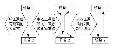
Figure 11-4 Simplex, Half-Duplex, and Full-Duplex Communications
Simplex communication uses a wire, and the sender and receiver of the signal have clear directionality. In other words, communication takes place in only one direction.
If the same transmission line is used as both the receiving line and the sending line, although the data can be transmitted in both directions, both parties of the communication cannot send and receive data at the same time. Such a transmission method is called half duplex. In the half-duplex mode, the transmitter and receiver at each end of the communication system are time-diverted to the communication line through the transceiver switch for direction switching.
When the data is transmitted and received separately by two different transmission lines, the two parties can both perform transmission and reception operations at the same time. This transmission method is full-duplex. In the full-duplex mode, the transmitter and the receiver are provided at each end of the communication system, so that data can be controlled to be transmitted in both directions simultaneously. Full-duplex mode does not need to switch direction.
Serial communication can be divided into two types, one is synchronous communication and the other is asynchronous communication. When using synchronous communication, all characters are grouped into a group so that characters can be transmitted one after another. However, a synchronization character is added at the beginning of each group of information. When there is no information to be transmitted, a null character is filled because of the synchronous transmission. No gaps are allowed. When asynchronous communication is used, the transmission interval between two characters is arbitrary. Therefore, some data bits are used as separation bits before and after each character. In comparison, when the transmission rate is the same, the information efficiency in the synchronous communication mode is higher than that in the asynchronous mode because the proportion of non-data information in the synchronous mode is relatively small. However, on the other hand, the synchronization method requires both sides of the information transmission must use the same clock for coordination, it is this clock to determine the location of each information bit in the synchronous serial transmission process. In this way, if you use the synchronous method, then you must also transmit the clock signal while transmitting data. In the asynchronous mode, the clock frequency of the receiver and the clock frequency of the transmitter do not have to be exactly the same, but as long as they are relatively similar, that is, they do not exceed a certain allowable range. In data transmission, asynchronous communication is widely used. The standard data format of asynchronous communication is shown in Figure 11-5.
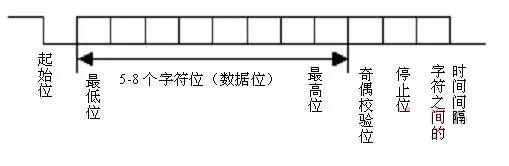
Figure 11-5 Asynchronous communication data format
As can be seen from the format shown in Figure 11-5, asynchronous communication is characterized by the transmission of one character character by character, and the transmission of each character always starts with the start bit and ends with the stop bit. There is no fixed time between characters. Interval requirements. Each time there is a start bit, followed by 5-8 data bits, followed by the parity bit, it can be an odd test, it can be even, or it can not be set, and finally it is 1 bit, or 1 bit Half, or 2-bit stop bits, followed by stop bits with indefinite length idle bits. Both the stop bit and the free bit are defined as high, which guarantees that there must be a falling edge at the start of the start bit to indicate the start of data transfer.
Guangzhou Bolei Electronic Technology Co., Ltd. , https://www.nzpal.com