Multisim is an advanced version of the electronic circuit simulation software EWB (Electronics Workbench), developed by Interactive Image Technologies in Canada. It offers users a comprehensive and integrated design environment, enabling them to build circuits, perform simulations, and analyze results all within a single platform. The simulation approach is highly practical, with components and instruments closely resembling real-world counterparts. The Multisim component library contains thousands of circuit elements and is fully compatible with PSpice, one of the most widely used circuit analysis tools. The software supports various types of analysis, such as transient, steady-state, time-domain, frequency-domain, noise, distortion, and discrete Fourier analysis. In this paper, Multisim is employed as the primary working platform for analyzing a second-order low-pass filter circuit. Additionally, it allows seamless data transfer from schematics to PCB layout tools like Ultiboard, offering an intuitive interface and user-friendly operation.
2. Circuit Design
The amplitude-frequency characteristic degradation rate of a first-order low-pass filter is only -20 dB/decade, which is far from ideal, resulting in poor filtering performance. To enhance the roll-off rate and bring the circuit closer to the ideal behavior, a second-order RC active filter is commonly used. This involves adding an additional RC network to the first-order configuration.
The circuit structure is illustrated in Figure 1. The upper section consists of an operational amplifier along with resistors R1 and Rf, both set at 16 kΩ. The lower part is a second-order RC filter composed of resistors R2 and R3 (4 kΩ each) and capacitors C1 and C2 (0.1 μF each). An AC voltage source with an adjustable amplitude of 1 mV and a series resistor of 1 kΩ is connected to the input.
3. Theoretical Analysis
3.1 Frequency Characteristics
The frequency response of the second-order low-pass filter is given by the following formula:
$$ H(j\omega) = \frac{A_{UP}}{1 + j\omega RC + (j\omega RC)^2} $$
where $ A_{UP} $ is the passband voltage gain, and $ f_0 $ is the characteristic frequency.
3.2 Passband Voltage Gain $ A_{UP} $
At low frequencies, the capacitors act as open circuits, making the circuit behave like a non-inverting amplifier. The passband voltage gain is calculated as:
$$ A_{UP} = 1 + \frac{R_f}{R_1} = 2 $$
3.3 Characteristic Frequency $ f_0 $ and Passband Cutoff Frequency $ f_P $
The characteristic frequency $ f_0 $ is determined by:
$$ f_0 = \frac{1}{2\pi\sqrt{R_2 R_3 C_1 C_2}} $$
And the cutoff frequency $ f_P $ is approximately equal to $ f_0 $, where the gain drops by 3 dB.
4. Multisim Analysis
4.1 Virtual Oscilloscope Analysis
Using the virtual oscilloscope in Multisim, the input and output signals are connected to nodes 1 and 3, respectively. At a frequency of 1 kHz, the output signal shows a significantly reduced amplitude compared to the input, indicating that the filter is effectively attenuating higher frequencies. When the input frequency is set to 1 Hz, the output voltage is 2 mV, confirming the theoretical gain of 2.
4.2 AC Analysis
By performing an AC analysis in Multisim, the amplitude-frequency characteristics of the circuit can be accurately observed. The maximum gain is found to be 6.02 dB, corresponding to a voltage gain of 2. The cutoff frequency is identified at approximately 148.5 Hz, aligning closely with the theoretical prediction.
4.3 Parameter Sweep Analysis
The parameter sweep function in Multisim allows for the analysis of how changes in component values affect the circuit's performance. For example, varying the capacitance of C1 results in different cutoff frequencies, while having minimal impact on the voltage gain. Similar effects are observed with other components such as C2, R2, R3, and Rf. These analyses provide valuable insights into the sensitivity of the circuit to component variations.
5. Conclusion
Through detailed analysis and simulation using Multisim, the results closely match the theoretical predictions. Multisim serves not only as a powerful tool for circuit design and simulation but also as an effective educational resource. Its integration into classroom teaching enhances multimedia-based instruction in electronics, offering a more interactive and engaging learning experience. By providing flexibility, real-time feedback, and high efficiency, Multisim significantly improves the quality of electronic circuit education, expanding both the depth and breadth of instructional content.
1500W power station
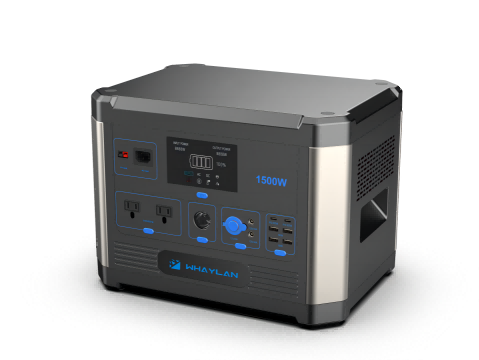
Whaylan 1500W portable solar power station.Large capacity, high endurance, a variety of ports, at any time for your need to charge the equipment. Completely say goodbye to the anxiety of outdoor electricity and devote yourself to an outdoor activity. At the same time, it can be equipped with solar panels to charge the power supply. The energy storage technology of lithium battery is combined with the clean renewable energy of solar energy to truly realize the enjoyment from day to night.
Suzhou Whaylan New Energy Technology Co., Ltd. Limited was founded in 2022,mainly specializes in designing and manufacturing of 3C electronic products,batteries,cables, power banks, portable power station, earphones, audio cables, type c products, adapters, car charger, other mobile accessories, OEM/ODM for top brands all over China and the world.
Whaylan is a member of USB-IF and WPC.Our factories are located in Dongguan and cover 10000 square meters, including about 400
well-trained workers,30 experienced engineers,35 QC employees, and 16 production lines. With the total capacity around 3 million pieces cables and power banks monthly.5-10 new designs will be launched each quarter to target updated market demand.
1500W power station,powerstation 1500 watt,1500w portable power station
suzhou whaylan new energy technology co., ltd , https://www.xinlingvideo.com