Car start/stop system power solution
To limit fuel consumption, some automakers have adopted the “Start/Stop†function in their next-generation models. These innovative new systems shut down the engine when the car stops, and automatically restart the engine when the driver's foot moves from the brake pedal to the accelerator pedal. This will help reduce fuel consumption during busy periods of urban driving and stop-and-go traffic.
But such systems present some unique engineering challenges for automotive electronics because the battery voltage can drop to 6.0 V or less when the engine is restarted. In addition, typical electronic modules include reverse polarity diodes to protect electronic circuitry in the event of a jump start and a jumper cable reversal. The diode causes the battery voltage to drop by another 0.7 V, making the downstream circuit voltage only 5.3 V or lower. Since many modules still require 5 V supply, there is not enough headroom to work properly.
One solution is to use a boost power supply. The boost supply accepts a lower input voltage and produces a higher voltage at the output. Suppliers are currently using some type of boost supply at the front end of the electronic module to enable it to function properly under voltage drop conditions caused by the start/stop system. The different options that designers can use for these start/stop systems, including low dropout (LDO) regulators, battery reverse protection schemes, and various boost options, are examined below.
Just like most engineering problems, there are many ways to solve problems. If the battery voltage drops to only 6 V at the input, then the preferred and simplest solution is to find a very low dropout linear regulator that requires only a 0.3 V margin. This approach is suitable for modules with lower current requirements, but for modules that require more current, designers need more options.
Another approach is to replace the standard PN junction diode for reverse cell protection at the front end with a Schottky diode or a P-channel MOSFET. The forward voltage drop of the Schottky diode is about half that of a standard rectifier, so it adds a voltage margin of a few volts. Switching to a Schottky diode is simple enough, because it usually fits on the same PCB pad as a standard diode without changing the wiring. However, P-channel MOSFETs (P-FETs for short) require changes to the PCB and require additional circuitry.

Figure 1: Battery reverse protection with P-channel MOSFET
Figure 1 shows the three components required, including P-FETs, Zener diodes, and resistors. A properly sized P-FET needs to be selected to handle the voltage applied to the input of the module and the required load current. In addition, it is important to take into account system thermal requirements because the power dissipation of the FET is equal to the square of the current multiplied by the on-resistance of the FET. The Zener diode protects the gate oxide of the MOSFET from operation caused by overvoltage conditions. Most P-FETs have a gate-to-source connection capable of handling 15 to 20 volts, so the Zener diode must be set to clamp before this point. The resistor pulls the gate down to ground to turn on the P-FET, but the size of the resistor must also be chosen appropriately. The impedance of the resistor should not be too low, because the impedance is too low, which will cause excessive current to pass through the Zener diode, thus breeding the power dissipation problem of the Zener diode. However, if the impedance of the resistor is too large, the conduction of the P-FET may not be as robust as possible in this case, and the idea of ​​this scheme is to reduce the voltage across the drain to the source.
It is likely that one of the above options, or a combination of certain solutions, will be suitable for a given application. But what happens if the input voltage actually drops below 5 V? Some manufacturers are investigating whether the input voltage drops to 4.5 V under cold cranking conditions. The three most common switching regulators are boost voltage supplies, buck/boost supplies, and single-ended primary inductor converter (SEPIC) supplies.
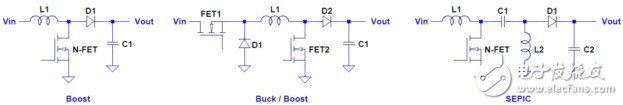
Figure 2: Different boost power supply topologies
The boost power supply uses one inductor, one N-channel MOSFET (ie, N-FET), one diode, and one capacitor. It's the simplest design, but it also has some drawbacks. If the output is shorted, there is no way to protect it because there is a direct path between the input and the output. In addition, when the input voltage rises above the output voltage set point, there is no way to prevent the output voltage from rising as the input voltage will pass through the inductor and diode to the output.
For example, most modules in a car must pass a load dump test. This test produces a voltage spike and is applied to the input voltage. In a boost supply, this voltage spike propagates to the output. Therefore, if a 40 V spike propagates along the line, any circuit connected to the output voltage must be able to handle such a high voltage.
Another possible switching regulator option is the non-inverted (non-invert TIng) buck/boost design. This design uses only one inductor and one capacitor, but requires two switches and two diodes. But this solution does allow the designer to avoid an increase in the output voltage when the input voltage rises above the output voltage. It can also use the first switch (FET1) to open the circuit to provide output short-circuit protection. The downside of this design is its energy efficiency, because it takes into account the loss of two diodes and two switches.
The SEPIC design is very similar in wiring to the direct boost converter, except that this design adds one hair extension inductor and one DC blocking capacitor. The downside of this design is the addition of an inductor and a capacitor, but on the plus side, there is no longer a problem with the output short circuit because the DC blocking capacitor is now serially connected to the output. In this way, the output is no longer affected by the input voltage, so it can be lower or higher than the input voltage.
It should be noted that although all switching topologies have been enumerated above, a battery reverse protection scheme is still needed because reverse current may flow from ground level to input voltage via the body diode on the back of the FET.
All in all, there are many issues to consider when starting/stopping the design of an alternator system. This article only discusses the power supply of electronic modules, but there are other issues that need to be addressed. For example, when the voltage drops, both internal and external lighting will dim. The problem of internal lighting flicker is also annoying but not critical, and the brake lights and headlamps affect safety, so the power supply needs to maintain the brightness of these internal and external lighting and continue to work. Advantageously, there are solutions on the market today that address these issues.
We offer Phone Glass Protector, iPhone Glass Screen Protector, Tempered Glass for iPhone
Features:
|
Feature |
Thickness: 0.33mm |
|
Hardness: 9H |
|
|
Anti-oil, easy absorption |
|
|
Super high-definition for true color display, enjoy your visual feast |
|
|
Our cell phone protective films can anti-smudge and anti-fingerprints protection |
|
|
Anti-scratch and explosion-proof |
|
|
Provide supreme and nice appearance , our tempered glass protector make people feel comfortable and smooth grip |
|
|
Bubble-free and easily absorb |
|
|
Lead time |
7-9 working days/ Sample lead time : 1-4 days |
|
Package |
crystal boxes and Blister box packing available |
|
Payment |
T/T, Western Union, L/C, PayPal |
Glass Screen Protector
Glass Screen Protector,Tempered Glass Screen Protector,Anti Fingerprint Glass Screen Protector,Iphone 6 Plus Screen Protector,Iphone 6 Screen Protector,Iphone 6S Screen Protector,Iphone Glass Screen Protector,Tempered Glass For Iphone
Hebei Baisiwei Import&Export Trade Co., LTD. , https://www.baisiweicable.com