Analysis of electric vehicle design environment and power management circuit
As Henry Ford said in 1923: “Even if you only save a few pounds of car weight... it means they can drive faster and consume less fuel.†This eternal truth is the lithium battery chemical industry with higher Specific energy (Joules/kg) leads the world to the next generation of more weight-efficient, plug-in electric vehicles.
But we still remember the lithium-ion battery explosion of laptops. When we consider the larger total energy of electric car batteries, the event is further amplified. This concern and other factors have contributed to the development of highly intelligent battery management systems (BMS). This battery management system needs to communicate with high-power battery charging systems to meet requirements such as safety, cost, battery life, car travel (aka mileage anxiety) and overnight charging – in order to achieve lower carbon emissions and higher Fuel economy needs to make all the painful concessions.
As automotive OEMs determine the requirements for next-generation battery management and charging systems, semiconductor companies are advancing product development that is expected to meet these requirements. This article will discuss the design requirements, architecture, and challenges associated with the development of high-power ("3kW), off-line battery chargers in plug-in hybrid electric vehicles (PHEVs) and show why digital power supplies are needed for such applications. Architecture.
Electric vehicle design environment
Electric vehicles generally refer to vehicles that are propelled using high-voltage batteries and electric motors. The advantage of this technique over a car powered by an internal combustion engine (ICE) is that the electric motor is much more efficient than the ICE in generating torque, especially during acceleration. In addition, electric vehicles can recover kinetic energy while driving, while other cars can only be lost in the form of heat.
Hybrid vehicles (HEVs), unlike emerging PHEVs, use lower capacity batteries and electric motors to assist with major ICE acceleration. This combined torque plus regenerative braking capability further improves fuel efficiency and reduces carbon emissions.
However, reducing emissions does not fully meet the latest legal requirements for zero emissions from automobiles. Therefore, as a new car, the power of PHEV comes entirely from clean grid energy1.
The so-called series electric car differs from the parallel HEV in that it does not mix torque from two sources. All propulsion torque comes from a larger electric motor, typically greater than 80 kW. In some cases, a performance-optimized small mileage extension ICE is added to solve the mileage limitation problem of pure electric vehicle batteries. The ICE acts as a generator to power the electric motor and charge the battery. Whether in PHEV or HEV, the addition of high-voltage batteries and electric motors has fundamentally changed the electrical, mechanical and safety systems of automobiles. This ultimately requires complex and highly intelligent power electronics and battery management systems.
Battery design challenge
In the past 100 years, engineers have improved the gasoline propulsion system. Now, OEMs and their suppliers have changed the way they used to, formed alliances, broke the rules, and concentrated on optimizing electric propulsion systems.
But the high cost of electric propulsion is reflected in product development and component complexity, requiring continuous management of tens of kilowatts of power with complex and fault-tolerant automotive intelligence and power electronics.
Consider the simple task of measuring the amount of oil in a conventional gasoline-powered car. Depending on the car, the fuel gauge may simply be a bimetallic strip driven by a heating coil connected to a transmitting component. In electric vehicles, the 'tank' is a high-voltage battery consisting of many battery cells (possibly 100 knots or more) connected in series/parallel. Accurate judgment of the state of charge (SOC) requires accurate voltage measurements (within a few millivolts) for each cell.
This is the job of the battery management system. The BMS is a high-precision system for reporting detailed information about the voltage, current and temperature of the battery unit to the central processor, and then the central processor is responsible for calculating the SOC of the battery (that is, the amount of fuel in the car). Failure to accurately measure the battery not only misreports the battery SOC, but also shortens battery service life or creates unsafe and potentially catastrophic conditions.
To avoid this, the industry has developed ICs that meet emerging standards such as ISO26262, which provide N+1 redundancy through hardware built-in test functions and safety-critical functions such as overvoltage/undervoltage monitoring of battery cells. Protection ensures that the system works reliably. If a battery in the battery pack is forced into a deep discharge state or is overcharged, the battery may be permanently damaged and may experience thermal runaway - self-destruction. Therefore, secondary protection is required in addition to the main battery monitoring system.
More advanced BMS will synchronize voltage and current measurements and serve as a means of continuously measuring battery impedance. Impedance is an important indicator of battery health (SOH).
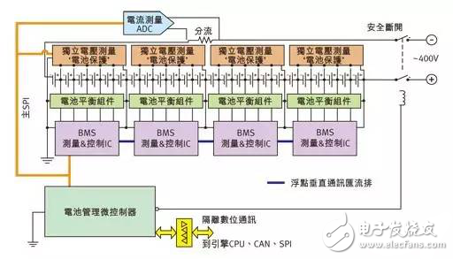
Figure 1: Battery management system for multi-cell quantities.
Figure 1 shows a typical cell configuration and BMS sufficient to measure battery SOC and SOH. Note that any battery cell in the series battery pack limits the entire battery pack capacity. In other words, if a battery cell reaches the maximum or minimum voltage before other batteries, the charge or discharge cycle must be interrupted. The cell balancing circuit (indicated in green in the figure) is used to ensure that all cells are uniformly charged and discharged.
We are saleing Membrane Switch for B&R,provides the product information.
Membrane Switch for B&R are widely used for medical and industrial equipment, research shows, machinery equipment, industrial control, man-machine interface, industrial automation integrated workstation, POS, CNC etc. we have a lot of Membrane Switch for B&R, standing some of our inventory stock.
Membrane Switch For B&R,Membrane Keypad For B&R,Membrane Keyboard For B&R
GUANGZHOU VICPAS TOUCH TECHNOLOGY CO.,LTD , https://www.touchsuppliers.com