Principle of stepping motor controlled by single chip microcomputer
Principle of stepping motor controlled by single chip microcomputer
This document introduces the working principle of Deng stepper motor and the characteristics of stepper motor controlled by single-chip microcomputer in detail. The stepper motor is a digitally controlled motor, which converts the pulse signal into an angular displacement, that is, given a pulse signal, the stepper motor rotates by an angle, so it is very suitable for single-chip microcomputer control.
Stepping motors can be divided into reactive stepping motors, permanent magnet stepping motors and hybrid stepping motors. The biggest feature of a stepping motor which is different from other control motors is that it is controlled by inputting a pulse signal, that is, the total rotation angle of the motor is determined by the number of input pulses, and the speed of the motor is determined by the frequency of the pulse signal. It has high-precision positioning, position and speed control, positioning retention, sensitive action, open loop control without relying on sensor positioning, high torque at medium and low speeds, high reliability, small size, high power and other characteristics, so that it has Wide range of applications.
1. The working principle of stepper motor
Stepper motor is a commonly used actuator in electromechanical control. Its purpose is to convert electrical pulses into angular displacement. Its drive circuit works according to control signals, which are generated by single-chip microcomputers. When the stepper driver receives a pulse signal, it drives the stepper motor to rotate a fixed angle in the set direction to control the commutation sequence, that is, the power-on control pulse must strictly follow a certain sequence to control the on and off of each phase. The angular displacement can be controlled by controlling the number of pulses, so as to achieve the purpose of accurate positioning. Control the steering of the stepper motor, that is, the given working mode is energized in a positive sequence, and the stepper motor rotates forward. If it is energized and commutated in a reverse sequence, the motor will reverse. To control the speed of the stepper motor, that is, to send a control pulse to the stepper motor, it will turn one step, and then send a pulse, it will turn another step, the shorter the interval between the two pulses, the faster the stepper motor will turn. At the same time, the speed and acceleration of the motor rotation are controlled by controlling the pulse frequency, so as to achieve the purpose of speed regulation.
2. Design plan
This design uses 51 single-chip AT89C51 (crystal oscillator frequency of 12MHZ) to control the four-phase six-wire stepper motor (internal resistance 33 ohms, step 1.8 degrees, rated voltage 12V). The square wave with time sequence output through the I/O port is used as the control signal of the stepper motor, and the signal drives the stepper motor through the chip ULN2003. ULN2003 is a high withstand voltage, high current Darlington display, composed of seven silicon NPN Darlington tubes. Each pair of Darlington in ULN2003 is connected in series with a 2.7K base resistor. It can be directly connected to TTL and CMOS circuits under a working voltage of 5V, and can directly process data that originally required standard logic buffers to process. ULN2003 has high working voltage and high working current, the sink current can reach 500mA, and can withstand a voltage of 50V when it is off, and the output can also run in parallel with high load current. The drive circuit of the stepping motor is formed through ULN2003, the circuit diagram is shown as in Fig. 1. Ports 25-28 of 51 are connected to the input terminals 1-4 of ULN2003. In addition, use the keyboard to control the state of the motor, and use the digital tube to display the motor's speed, and use the 74LS164 as a 2-digit single digital tube display drive. 74LS164 has a latch, and the use of serial connection can save I/O port resources. Its circuit diagram is shown as in Fig. 2. Send data to CLK and DATA through the TXD and RXD ports of 51.
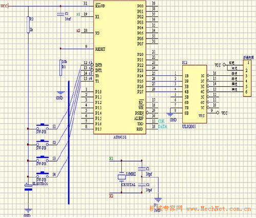
Figure 1 51 single chip microcomputer control stepper motor circuit diagram
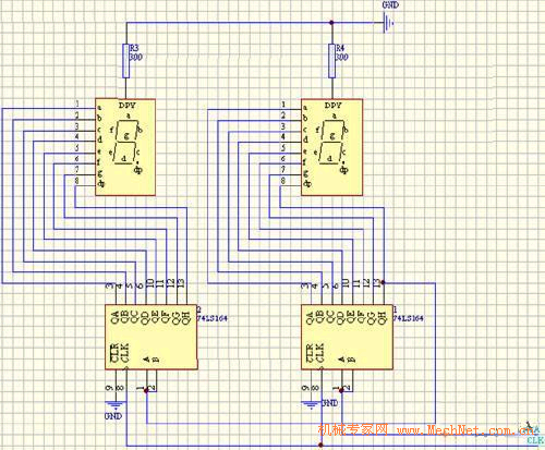
Figure 2 shows the circuit diagram
3. Expected goals
Connect Figure 1 and Figure 2 to realize: press the start button, the motor rotates, press the plus 1 button, the speed increases, press the minus 1 button, the speed decreases, the maximum speed is 100 rpm, the minimum speed is 25 Rpm, press the stop button, the motor will stop. The speed value is displayed on the digital tube.
Based on the above-selected schemes, the overall process is shown in Figure 3.

Figure 3 System circuit flow chart
Concluding remarks
The designed stepper motor can basically achieve the expected goal. After debugging and modification, there are still problems. For example, when the switch is pressed, it will be unstable, the speed is sometimes messy, and the display is sometimes not ideal. The next work is in the software. And hardware and other aspects are modified to fully achieve the expected goals.
Morden Noodle Maker,Portable Kitchen Tools,Household Kitchen Tools,Commercial Juice Machine
JOYOUNG COMPANY LIMITED , https://www.globaljoyoung.com