Max7219 drive digital tube program (51 single-chip + STM32 MAX7219 digital tube program case)
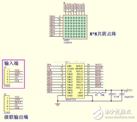
Digital tube module circuit diagram
/************************************************* ****************/
Updated Time: December 12, 2015
Function: Driving the digital tube through the MAX7219
************************************************** ****************/
#include "delay.h"
#include "sys.h"
#include "usart.h"//Serial communication
#define Max7219_pinCLK PAout(5)
#define Max7219_pinCS PAout(3)
#define Max7219_pinDIN PAout(7)
/************************************************* ***************************
* Name: SPI1_Init(void)
* Function: STM32_SPI1 hardware configuration initialization
* Entry parameters: none
* Export parameters: none
* Description: STM32_SPI1 hardware configuration initialization, using 3V3
************************************************** **************************/
Void SPI1_Init(void)
{
SPI_InitTypeDef SPI1_InitStructure;
GPIO_InitTypeDef GPIO_InitStructure;
// Configure SPI1 pin
RCC_APB2PeriphClockCmd(RCC_APB2Periph_AFIO|RCC_APB2Periph_GPIOA, ENABLE);
RCC_APB2PeriphClockCmd(RCC_APB2Periph_SPI1, ENABLE);
GPIO_InitStructure.GPIO_Pin=GPIO_Pin_3;
GPIO_InitStructure.GPIO_Speed=GPIO_Speed_50MHz;
GPIO_InitStructure.GPIO_Mode=GPIO_Mode_Out_PP;
GPIO_Init(GPIOA,&GPIO_InitStructure);
GPIO_InitStructure.GPIO_Pin=GPIO_Pin_4|GPIO_Pin_5|GPIO_Pin_6|GPIO_Pin_7;//SPI1 related pin
GPIO_InitStructure.GPIO_Speed=GPIO_Speed_50MHz;
GPIO_InitStructure.GPIO_Mode=GPIO_Mode_AF_PP;//Push-pull multiplexing function
GPIO_Init(GPIOA,&GPIO_InitStructure);
SPI1_InitStructure.SPI_Direction=SPI_Direction_2Lines_FullDuplex;//Set SPI one-way or two-way data mode; SPI is set to two-wire bidirectional full duplex
SPI1_InitStructure.SPI_BaudRatePrescaler=SPI_BaudRatePrescaler_64;//Define the baud rate prescaler value; baud rate prescaler 64
SPI1_InitStructure.SPI_DataSize=SPI_DataSize_8b;//Set the data size of the SPI; SPI send and receive 8-bit frame structure
SPI1_InitStructure.SPI_Mode=SPI_Mode_Master;//Set SPI working mode; set as master SPI
SPI1_InitStructure.SPI_FirstBit=SPI_FirstBit_MSB; //High MSB first
SPI1_InitStructure.SPI_CPOL = SPI_CPOL_High; //Select the steady state of the serial clock, the clock is floating high
SPI1_InitStructure.SPI_CPHA = SPI_CPHA_2Edge; // data capture on the second clock edge
SPI1_InitStructure.SPI_NSS = SPI_NSS_Soft; //Use software mode,
SPI1_InitStructure.SPI_CRCPolynomial = 7; // Polynomial calculated by CRC value
SPI_I2S_DeInit(SPI1);
SPI_Init(SPI1, &SPI1_InitStructure); //Initialize according to the specified parameters
SPI_Cmd (SPI1, ENABLE); //SPI enable
}
This code demonstrates how to interface an 8-digit digital display using the MAX7219 driver IC with an STM32 microcontroller via hardware SPI. The MAX7219 is a common chip used for driving LED displays, and it simplifies the process by handling the multiplexing and current control internally. The SPI communication is configured to work in full-duplex mode with a specific baud rate and clock polarity. This setup allows for efficient and reliable control of the display. The configuration includes setting up the necessary GPIO pins, initializing the SPI peripheral, and enabling it for operation. The code serves as a foundational example for integrating digital displays into embedded systems.Micro COB LED Display,Micro COB LED sign display,COB LED display video wall,Small Pitch COB LED signage,Mini COB LED display Panel,Fine pixel pitch Micro COB LED screen
Shenzhen Xinfei Century Technology Co., Ltd. , https://www.rgbdancing.com