Max7219 drive digital tube program (51 single-chip + STM32 MAX7219 digital tube program case)
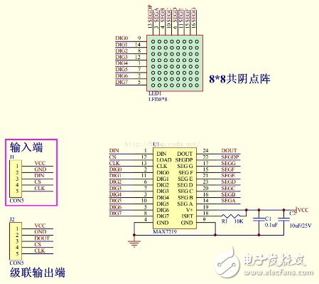
The circuit diagram of the digital tube module is shown below.
/************************************************* ****************
Updated Time: December 12, 2015
Function: Driving the digital tube via MAX7219
************************************************** ****************/
#include "delay.h"
#include "sys.h"
#include "usart.h" //Serial communication
#define Max7219_pinCLK PAout(5)
#define Max7219_pinCS PAout(3)
#define Max7219_pinDIN PAout(7)
/************************************************* ***************************
* Name: SPI1_Init(void)
* Function: Initialize STM32 SPI1 hardware configuration
* Entry parameters: none
* Export parameters: none
* Description: Configure SPI1 for 3.3V operation
************************************************** **************************/
void SPI1_Init(void)
{
SPI_InitTypeDef SPI1_InitStructure;
GPIO_InitTypeDef GPIO_InitStructure;
// Configure SPI1 pins
RCC_APB2PeriphClockCmd(RCC_APB2Periph_AFIO | RCC_APB2Periph_GPIOA, ENABLE);
RCC_APB2PeriphClockCmd(RCC_APB2Periph_SPI1, ENABLE);
GPIO_InitStructure.GPIO_Pin = GPIO_Pin_3;
GPIO_InitStructure.GPIO_Speed = GPIO_Speed_50MHz;
GPIO_InitStructure.GPIO_Mode = GPIO_Mode_Out_PP;
GPIO_Init(GPIOA, &GPIO_InitStructure);
GPIO_InitStructure.GPIO_Pin = GPIO_Pin_4 | GPIO_Pin_5 | GPIO_Pin_6 | GPIO_Pin_7;
GPIO_InitStructure.GPIO_Speed = GPIO_Speed_50MHz;
GPIO_InitStructure.GPIO_Mode = GPIO_Mode_AF_PP;
GPIO_Init(GPIOA, &GPIO_InitStructure);
SPI1_InitStructure.SPI_Direction = SPI_Direction_2Lines_FullDuplex;
SPI1_InitStructure.SPI_BaudRatePrescaler = SPI_BaudRatePrescaler_64;
SPI1_InitStructure.SPI_DataSize = SPI_DataSize_8b;
SPI1_InitStructure.SPI_Mode = SPI_Mode_Master;
SPI1_InitStructure.SPI_FirstBit = SPI_FirstBit_MSB;
SPI1_InitStructure.SPI_CPOL = SPI_CPOL_High;
SPI1_InitStructure.SPI_CPHA = SPI_CPHA_2Edge;
SPI1_InitStructure.SPI_NSS = SPI_NSS_Soft;
SPI1_InitStructure.SPI_CRCPolynomial = 7;
SPI_I2S_DeInit(SPI1);
SPI_Init(SPI1, &SPI1_InitStructure);
SPI_Cmd(SPI1, ENABLE);
}
This code sets up the SPI interface on an STM32 microcontroller to communicate with a MAX7219 chip, which is commonly used to drive 8-digit LED displays. The MAX7219 simplifies the control of multiple digital tubes by handling the multiplexing and brightness control internally. This setup allows for easy display of numbers or characters on the digital tubes using a minimal number of I/O pins. The SPI communication is configured for full-duplex mode with a clock polarity of high and data captured on the second edge of the clock signal. The software NSS (chip select) is enabled to manage the communication with the MAX7219 module. This implementation can be expanded to include more complex display patterns, scrolling text, or dynamic updates based on user input or sensor data.
Micro GOB LED Display,Micro GOB LED digital wall,Small Pitch GOB LED signage,Micro GOB LED display signage,Mini GOB LED digital screen,fine pixel pitch Micro GOB LED screen
Shenzhen Xinfei Century Technology Co., Ltd. , https://www.rgbdancing.com