Design of Embedded Alarm System Based on GPRS
In order to realize the real-time monitoring of the security situation of the home environment and to automatically dial for voice prompts or send alarm messages when an alarm occurs, an embedded telephone alarm system based on GPRS is designed. The system uses the SoC (On-Chip System) MCU C8501F020 as the control and processing core, and uses 2.4 GHz digital wireless transmission technology to connect the sensors, receive the signals collected by the sensors, and monitor the surrounding environment. At the same time, the system combines GPRS short message function and fixed telephone network to achieve reliable transmission of alarm information and remote control. The system has also designed a terminal interface, which is convenient for users to set system passwords or preset alarm phone numbers, as well as generate and query system alarm logs.
As an important part of smart home, alarm system is playing an increasingly important role in daily life. Today's commonly used alarm system uses a single-chip computer to control the fixed telephone network to transmit alarms. The stability and reliability are relatively low, and the human-computer interaction is difficult and the operation is complicated. This directly weakens its application value in real life, so The alarm system urgently needs to improve and optimize the design plan to promote its development.
This paper designs an intelligent alarm system that uses an enhanced single-chip microcomputer as the control core and combines sensor technology, digital wireless technology, GSM mobile communication network, fixed telephone network, embedded technology and computer control technology. Compared with the previous telephone alarm system, the system uses GPRS short message function to make up for the shortcomings of fixed-line alarm. It has been strengthened and perfected in function and performance, improved stability and reliability, and improved human-computer interaction interface, simplifying users Operations when managing the system.
1 System Overview
The system uses an enhanced single-chip microcomputer as the system's processor to improve the stability and reliability of the system's work, and minimize the false alarm and false alarm rates of the system. The system cooperates with multiple sensors such as gas, smoke, door magnet, infrared, and ultrasonic to monitor the safety of the environment in real time, and combined with the fixed telephone network and GSM network to realize the voice of fire, theft and various emergency situations Alarm and SMS reminder. The system also provides users with an easy-to-operate computer terminal interface, reducing the operational complexity of user management and settings. In addition, the system also has an alarm log. After entering the password through the system terminal interface and verifying the success, the user can select the date to view the system alarm log of the day, and to a certain extent, realize alarm forensics. The system mainly has 6 specific functions:
(1) Combining digital wireless technology and sensor technology to monitor the safety of the home environment in real time;
(2) After receiving the alarm signal, the central Controller automatically dials the preset telephone number through the fixed telephone network for voice alarm or sends a short message reminder through the GPRS communication module;
(3) With automatic off-hook and DT MF decoding function, users can dial the phone to remotely control the system, such as: alarm pre-processing, release system alarm monitoring;
(4) Set or modify the password, preset or modify the phone number through the system terminal interface or the system keyboard;
(5) Record and query the alarm log;
(6) The disconnection detection function automatically detects the abnormal connection of the system to the telephone network.
2 System design and implementation plan
The system uses the MCU C8051F020 minimum system as the core control circuit to reduce the interference caused by the electromagnetic radiation of the MCU to the digital wireless circuit and improve the stability of the system. The sensor group and the digital wireless transceiver module form an environmental monitoring circuit to monitor the environmental safety status. The GPRS communication module and DT MF dual-tone multi-frequency codec circuit form the alarm information transmission channel of the system. The GPRS communication module sends short messages to the user's mobile phone via the GSM network to transmit alarm information. DT MF dual tone multi-frequency codec circuit realizes automatic dialing and remote control through fixed telephone network. The telephone interface circuit includes a disconnection detection circuit, a ringing detection circuit, and an automatic off-hook circuit to realize disconnection detection, ringing detection, and automatic off-hook. The voice circuit is used for alarm prompt sound storage and playback control. Figure 1 is a block diagram of the overall design of the system.
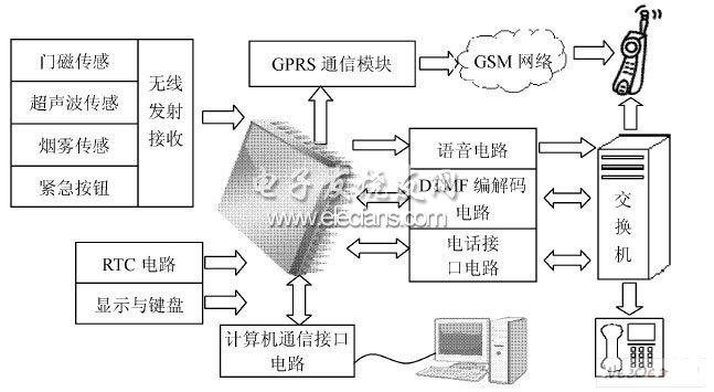
Figure 1 block diagram of the overall design of the system
2. 1 System hardware design
The system is mainly composed of 5 hardware modules: digital wireless transceiver circuit, GPRS interface circuit, DTMF dual-tone multi-frequency codec circuit, telephone interface circuit, voice circuit.
2. 1. 1 Digital wireless transceiver circuit
The system uses a 2.4 GHz half-duplex digital wireless transmission module with nRF24L01 as the core. nRF24L01 has 6 control signal lines, 4 pins of SPI bus: CSN (SPI enable), SCK (SPI clock), MOSI (master output slave input) and MISO (master input slave output); IRQ is after receiving data The generated interrupt signal is for query by the single chip microcomputer; CE is the chip select signal; set it low to turn on the data transmission module. The MCU configures the internal registers of nRF24L01 and transmits and receives data through the SPI serial bus.
In the wireless transmission circuit connected to the sensor, when the alarm occurs, the node MCU is triggered to control the nRF24L01 digital wireless transmission module to transmit the local node address and the collected alarm signal; in the wireless receiving circuit, C8051F020 communicates directly with nRF24L01 to receive the sensor node Address and alarm information, determine the alarm type by identifying the node address.
2. 1. 2 GPRS module interface circuit
After receiving the alarm signal sent by the sensor, the central processor controls the GPRS communication module, and sends a short message to the user's mobile phone terminal for alarm prompt through the GSM network.
The single-chip microcomputer control circuit is connected with the GPRS communication module through the UART interface. However, since the signal line of the GPRS module is 12 V S232 level, and the level of the single chip microcomputer is 3.3 V, it is necessary to use MAX3232 for level conversion. When an alarm occurs, the single-chip microcomputer sends the control command and short message content to the GPRS communication module through the serial port; the GPRS communication module recognizes the control command and sends a short message to the user according to the short message content.
2. 1. 3 DTMF dual tone multi-frequency codec circuit
DT MF dual tone multi-frequency codec circuit is mainly composed of MT 8888, including DTMF coding circuit, DTMF decoding circuit and ringtone recognition circuit. The coding circuit realizes automatic dialing, and the decoding circuit realizes remote control instruction recognition. The ring tone recognition circuit can correctly identify the dial tone, busy tone, and ring back tone.
During automatic dialing, the single-chip microcomputer sends the called number to the sending data register, synthesizes the DTMF signal, and transmits it to the program-controlled switch in the telephone network through the telephone interface after amplification to realize dialing. During remote control, the remote DT MF control signal is filtered by a high-frequency and low-frequency filter, and then encoded by a digital encoder to obtain the binary code of the corresponding control command, which is stored in the receive data register and an interrupt signal is generated at the IRQ port of MT 8888 After the microcontroller responds to the interrupt, it reads the data in the received data register and recognizes the control command. During ringtone recognition, a 450 Hz sine ringtone signal is input from the DTMF IN port and passes through a filter with a center frequency of 450 Hz and a bandwidth of 250 Hz. If the signal falls within the passband of the filter, the IRQ port output is the same Frequency square wave.
2. 1. 4 Telephone interface circuit
The telephone interface circuit includes an automatic off-hook circuit, a ringing detection circuit and a disconnection detection circuit.
The automatic off-hook circuit realizes analog automatic off-hook. When dialing an alarm or remote control, the system automatically off-hook and accesses the telephone network. During remote control, the ringing detection circuit can detect the phone ringing signal, and thus automatically pick up the phone. The ringing detection circuit is mainly composed of a high-speed optocoupler 6N138 and a voltage comparator LM393. According to the protocol of the program-controlled switchboard, the AC ringing signal is a sine wave of 25 Hz, 90 V. After the ringing signal passes through the DC isolation capacitor and the voltage limiting resistor, the photocoupler is driven, and a pulse is generated at the logic output terminal of the photocoupler. After being shaped by the voltage comparator, a square wave pulse is obtained. The pulse signal is input into the single-chip microcomputer, and the single-chip microcomputer can count the pulses, and automatically off-hook after counting a certain number of pulses. When the system is not normally connected to the telephone network, the disconnection detection circuit can automatically detect the fault and prompt.
2. 1. 5 Voice circuit
The system uses ISD1760 as a voice recording and playback chip. The MCU is connected to the ISD1760 through the SPI serial bus, transmits SPI commands, configures internal registers and implements voice recording and playback. As an SPI slave, ISD1700 can implement almost all key operations through these SPI commands.
Some SPI commands: such as PLAY, REC, ERASE, FWD, RESET, GLOBAL_ERA SE operation is similar to the corresponding independent key operation, in addition SET_REC, SET _PLAY, SET _ERASE command allows the user to specify the start and the recording and playback and erase End address.
When the system initializes the settings, it should first allocate the corresponding storage start and end addresses according to the length of various prompt tones by means of table lookup. And provide users with recording interface and control interface through hardware. When dialing an alarm, address and play the corresponding prompt tone according to the alarm type.
2. 2 System software design
2. 2. 1 System main program
After the system is powered on, it first delays 100 ms to allow the microcontroller and peripheral circuits sufficient time to reset. During the system initialization process, the external interrupts 6, 7 of the C8051F020 and serial port interrupts are enabled, and each interrupt request flag is reset. External interrupt 6 handles remote control, external interrupt 7 handles alarms, and serial interrupt handles PC control commands. Cyclically scan the interrupt flag bits of each channel. If the interrupt request flag bit is set, transfer to the corresponding interrupt service routine. as shown in picture 2.
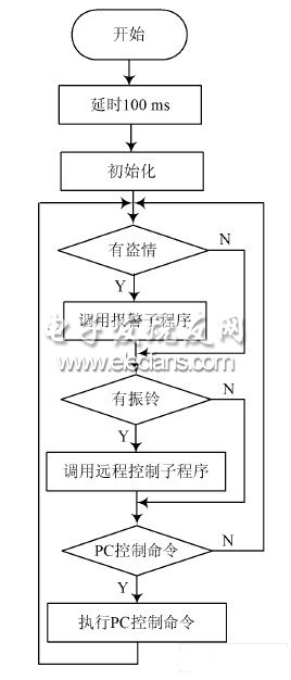
Figure 2 System main program flow chart
DELIGHT All-In-One series integrated Solar Street Light. All
in one design
Mono Solar Panel, led lamp, Lithium Battery and
controller all in a box
Put the lamp on pole and tighten screws, then it
works
No need any cable, easy maintenance
With PIR motion sensor, full power output if any
motion, other time is 30%
For public lighting: gardens, park, beaches,
roads, farm, walking street, car paring, etc
All-In-One Street Light,All In One Solar Street Light,All-In-One Solar Led Street Light,All-In-One Solar Street Light
Delight Eco Energy Supplies Co., Ltd. , https://www.cndelight.com