Design of TCP / IP Ethernet LCD electronic label system
In recent years, due to the development of e-commerce, the logistics industry has shown the characteristics of popularization of JIT delivery, small batches, multiple varieties, and high-frequency cargo transportation. In actual production operations, the handling of small batches, multiple varieties, and high-frequency goods is always a problem. Existing electronic label systems use fieldbus technology in control. But this technology has many deficiencies in information integration, such as:
â‘ There are too many existing fieldbus standards. The IEC international standard contains only 8 types, which cannot be unified into a single standard. The coexistence of multiple fieldbuses is a foregone conclusion.
â‘¡ Different types of fieldbus devices are equipped with dedicated communication protocols, which are not compatible with each other, cannot interoperate, cannot work together, and cannot seamlessly integrate information.
In order to solve the integration problem of multiple fieldbuses in the same control system, in some projects, some standard technology (such as OPC technology, etc.) is usually used to develop an interface that can connect its fieldbus. However, the fieldbus standards are not completely unified, and a large number of interfaces need to be developed to meet the needs of different industrial control objects. Therefore, we have proposed an Ethernet LCD electronic label system based on TCWIP.
1. Ethernet LCD electronic label auxiliary picking system based on TCP / IP
The Ethernet LCD electronic label based on TCP / IP is a set of liquid crystal display device installed on the storage. It displays the effective parameters such as the type and quantity of items to be picked, so as to guide the picking staff to complete the picking work correctly, quickly and easily. Figure 1 shows the LED electronic label picking system in actual production.
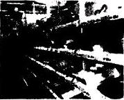
Figure 1 Electronic label picking system
In our system, the Ethernet / IP used is an open industrial network that supports both I / 0 and data exchange. The Ethernet switch is used to achieve point-to-point connection between devices and can support lOMb / s and 100 Mb at the same time. / s Ethernet commercial products facilitate the high-speed transmission of large amounts of data, as shown in Figure 2.
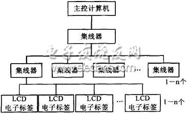
Figure 2 TCPIP-based Ethernet LCD electronic label system structure diagram
This entire system has the following advantages:
â‘ Standardization. Standardized underlying communication protocols, standardized components such as hubs or switches.
â‘¡ Simple structure, high stability and reliability.
â‘¢ Open structure, high bandwidth and good interchangeability.
â‘£ Simple wiring and convenient management.
⑤ Low cost.
2. Design of Ethernet LCD electronic label software based on TCP / IP
Software reuse has always been the dream technology of software programmers. The design pattern solves this problem for us to some extent, because it describes a problem that recurs repeatedly around us and the core of the solution to the problem. As can be seen from the network structure of Figure 2, the entire TCP / IP-based Ethernet electronic label system directly controls each LCD electronic label unit from a computer through a network card, so it has full openness, low cost, high bandwidth and stability High performance and reliability, simple wiring, high operating efficiency, convenient management, and low cost. In the logistics sorting system, accurate, rapid, and timely display of information such as item type, name, quantity, and system working status is the basic condition for ensuring the normal operation of the logistics system and improving the efficiency of the system. Therefore, stability and reliability are the basic principles of our design.
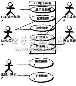
The function of the system in control can be simplified as:
Main control computer:
(1) Receiving the data returned from each LCD electronic label unit;
(2) Send master data information to each LCD electronic label unit downward.
LCD electronic label:
(1) Display the type, name, quantity, graphics or other relevant information of the items to be sorted;
(2) Communicate with the network card of the host computer to upload and receive data;
(3) Communication conflict detection (CSMA-CD);
(4) The input device generates corresponding input, such as buttons, keyboard, etc .;
(5) The output device produces corresponding output, such as speakers, four-color lights, etc.
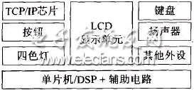
Figure 3 Structure of LCD electronic label based on TCPIP
Figure 3 shows the hardware structure of an Ethernet LCD electronic tag based on TCP / IP, which is mainly composed of an LCD display unit, a TCP / IP communication chip, input devices (such as buttons, keyboard), and output devices (such as speakers, four-color lights, etc. ) And other peripherals and single-chip DSP and other service circuits. The use case diagram of the entire system is shown in Figure 4.
The Rockwell Controllogix processor provides an optional user Memory Module (750K to 8M bytes) that can solve application problems with a large number of input and output points systems (up to 4000 analog and 128000 digital bits). The processor can control local input and output and remote input and output. The processor can monitor input and output in the system via Ethernet EtherNet / IP, ControlNet ControlNet, DeviceNet DeviceNet, and Remote I/O Universal Remote I / O.
When there are multiple processor modules in the Controllogix chassis, and even if there are multiple processor modules in the ControlNet network of the control network, all processors can read input values from all input modules. Any one processor can also control any specific output module. The system configuration specifies which processor is controlled by each output module.
The ControlLogix system is a rack-mounted, modular installation. The Controllogix I/O Modules are modularly mounted. The power module is mounted directly to the left side of the ControlLogix chassis. The Controllogix chassis is available in five types of 4, 7, 10, 13 or 17 slots. The module can be inserted in any slot of the rack. The maximum number of channels for Controllogix I/O modules is 32 channels. The mechanical lock of the removable terminal block of each module prevents the application of erroneous voltages to the module. Input and output modules can be hot plugged.
Rockwell Allen-Bradley: SLC500/1747/1746 MicroLogix/1761/1763/1762/1766/1764
CompactLogix/1769/1768
Logix5000/1756/1789/1794/1760/1788,PLC-5/1771/1785 and so on.

Rockwell Allen-Bradley
Rockwell Allen-Bradley,Processor Controll,Rockwell Automation Allen-Bradley,Allen-Bradley Equipments
Xiamen The Anaswers Trade Co,.LTD , https://www.answersplc.com