Driver integrated circuit for color PDP display system
In recent years, color PDP technology has continued to advance, and large wall-mounted TVs, HDTVs, and large display devices for multimedia displays using color PDPs are nearing completion. Since 1995, the world's major manufacturers have successively built lines to produce various types of color PDPs. These achievements are not only attributed to the successful development of the color PDP display itself and the establishment of production technology, but more importantly due to the development of driving integrated circuit technology. For a good performance PDP color TV, its driver integrated circuit system accounts for 70-80% of the total cost.
Color PDP displays can be divided into two types according to their structure, namely AC type color PDP and DC type color PDP (AC type and DC type). According to the driving method, it can be divided into two types: row sequential driving mode and storage driving mode.
A color PDP is an active light emitting device whose luminance is proportional to the light emitting time of each pixel. In general, when the row order of the matrix plane is driven, the brightness of the scan line decreases as the scan line data increases. Therefore, whether it is an AC or DC color PDP, a memory drive is used to increase the actual lighting time, thereby achieving high brightness.
The memory drive mode basically consists of three cycles of writing, illumination sustaining and erasing. The function of the driving integrated circuit is to apply a timing, periodic pulse voltage and current to the color PDP.
To this end, there are two groups of driver integrated circuits for color PDPs: the first group is an address driver that processes display data, also called a column driver; the second group is a scan driver that is responsible for scanning and sustain discharge during writing, also called a row driver. .
This article focuses on several driver integrated circuits for SN and μPD series color plasma display panels. At the same time, the three-electric and structural drive circuits will also be introduced.
1 color PDP driver integrated circuit structure and performance
1.1 Structural characteristics
1 is a basic structure of a color PDP driving integrated circuit.
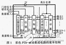
The internal structure of the driver is usually divided into two parts: one is a logic circuit for controlling the display screen signal and processing display data, and the other is a drive circuit for shifting the signal level and applying a pulse required for illumination to the display screen. Especially in the driving part, in order to make the color PDP gas discharge, it is necessary to provide a high voltage, so this structure requires a special integrated circuit process technology, which is different from the general logic integrated circuit, and the specific special performance is as follows:
â—High withstand voltage output
The high voltage output capability of a color PDP driver is its most important and basic performance, which is entirely determined by the structural characteristics of the color PDP itself. Therefore, manufacturers of color PDPs and manufacturers of semiconductor integrated circuits are required to establish a close cooperative relationship in order to jointly develop a driving integrated circuit of a color PDP.
Current drives have ensured the need for color PDPs. As the structure of the color PDP itself improves, the required driving voltage will decrease, and at the same time, the development of the driver is also moving toward optimization.
Taking AC-PDP as an example, the output withstand voltage of the address drive is 60-100V, the output source and leakage current are between 10 and 30mA, and the output voltage of the scan driver is 150-200V. Output source and leakage current Both are 200 to 400 mA, and the output current is largely dependent on the size of the display used and the switching pulses applied to the driven display electrodes.
â—Logical part
The performance of the logic portion of the driver is typically represented by the maximum clock operating frequency fmax of the shift register (the circuit that converts the serial signal to a parallel signal). In a CMOS logic circuit, the smaller the gate length (L), the larger the fmax, and therefore, the smaller the area of ​​the integrated circuit chip and the power consumption of the circuit, the more advantageous.
At present, the practical driver logic portion has a gate length L of 1.0 to 2.5 μm and fmax of 20 to 36 MHz. Such speeds, for the address drivers necessary for HDTV and high-precision data display, can fully meet the requirements of data shifting.
â—Power consumption of color PDP driver IC
In order to effectively utilize the characteristics of the flat display color PDP, the power consumption of other electronic components not related to display should be designed to be as small as possible. Because the power consumption of the drive itself will affect the display performance of the entire color PDP.
The power consumption of the current portion of the color PDP is roughly divided into three parts: (1) logic portion; (2) level shift register; and (3) high voltage driving portion. All three should reduce power consumption. Under normal circumstances, the logic part consumes less than 20mW (high-voltage 64-output start-up display board), and the level shift register part should be below 200mW. As for the inefficient power consumption of the high-voltage driving circuit due to the charging and discharging of the capacitive portion of the display, the power-distributed driving method (using a current switching circuit, etc.) has been able to satisfy the display of the color PDP under the natural heat-dissipating condition of the 100-pin plastic package. demand.
â—crosstalk phenomenon
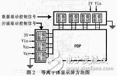
High-voltage CMOS driver integrated circuits often have mutual crosstalk in the system. As shown in FIG. 2, the color PDP screen includes a total of four or more power supply systems including high voltage. As long as the driver circuit makes them work, it will generate a large amount of crosstalk noise, causing mutual influence between the systems. In addition, the color PDP display as the load of the driving area is also distinct in the state of discharge and non-discharge, which also contributes to the occurrence of crosstalk.
In order to overcome the crosstalk phenomenon, the driving integrated circuit of the color PDP adopts more strict control measures in design and process than the ordinary integrated circuit. For example, the development of integrated drive circuits while developing special high-voltage-resistant processes has also given special attention to component structure design and circuit layout on integrated circuits. In addition, it is also necessary to suppress the capacitance in the integrated circuit as much as possible, and to cut off a bus or the like which may function as a semiconductor switching element.
â—Power recovery
In the driving process of a color PDP, it is necessary to reduce the power consumption that is useless for illumination as much as possible. In addition to the loss of discharge energy to luminescence energy conversion, the reactive power mainly comes from the charge and discharge of the electrode and the charge and discharge of the capacitor. The values ​​of the two parasitic loads, the resistive component and the capacitive component, are determined by the inherent structure of the display itself. It is impossible to improve the resistance component from the driver side. However, for the charging and discharging of the capacitor, the driver can try to recover a part, so that the power recovery circuit can be designed inside the driver, but the driving integrated circuit itself cannot generate parasitic load when recycling.
â—Power sequence
In a color PDP system, a total of four or more power sources (including high-voltage power supplies) are co-located in one system, and the power supplies operate in synchronization with the specified timing. Careful consideration should be given to the order in which the power is turned on and the protection in case of erroneous operation during system design. In particular, a driver directly connected to a color PDP display, if a malfunction occurs, not only destroys the integrated circuit itself, but also destroys the display and the entire system. Therefore, the drive should have fail-safe features and the ability to sequentially disconnect the power supply.
1.2 PDP driver IC
a. Addressing driver integrated circuit SN755831
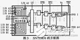
Figure 3 shows an internal functional block diagram of the address drive integrated circuit SN755831, which is a technical parameter thereof.
The driver has 64 ports, three-state, maximum withstand voltage of 160V output, and its logic circuit is composed of 5V CMOS devices, which can directly input data from color PDP signal processing system.
In addition, the internal control of the integrated circuit can eliminate the penetration current when the high voltage switch is used; the SN755831 can use the TSC terminal to complete the high impedance mode of the output. Due to the dielectric separation process, the output clamp diode inside the SN755831 avoids crosstalk.
b. Scanning drive SN755834
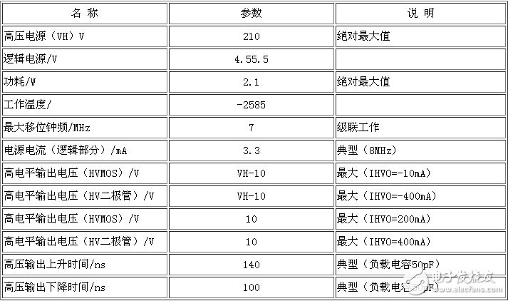
4 is an internal block diagram of a 64-port scan driver SN755834 with a maximum withstand voltage of 210V, and Table 2 is its main parameter. As a scan driver, its output withstand voltage is sufficient to drive a 100cm-level display. In addition, the SN75834 has a 200mA drain current capability and a 400mA output current diode.
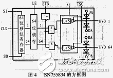
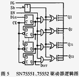
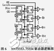
Table 1 Technical parameters of SN755831
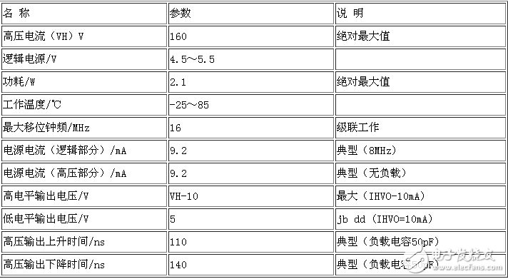
Table 2 Required parameters of the scan driver SN755834
The SN755834's own power consumption is very low, and it can fully drive a color PDP display in a naturally cooled state in a 100-pin plastic package.
LED downlight is application of a new type of LED Light source on the basis of traditional tube light of the development of improved products, compared with traditional tube light has the following advantages: energy saving, low carbon, long life, good color rendering and fast response.
LED Downlight, a design more beautiful light, installation to keep building decoration of the overall unity and perfect, does not destroy the set of lamps and lanterns, light hidden inside the building decoration, light source is not exposed, no glare, the visual effect of soft and uniform
The common LED downlight are:led recessed downlight, wall-mountable LED downlight.Both LED downlights are suitable for shopping malls, office building , hotels, homes , conference rooms and exhibition spaces and so on.
LED Downlight
LED Downlight,Aluminium LED Downlight,LED Dimmable Downlight,Round LED Downlight
Wenzhou Korlen Electric Appliances Co., Ltd. , https://www.korlenelectric.com