Design and Simulation of Signal Conditioning Circuit for Interferometric Fiber Optic Disturbance Sensor
In modern sensing systems, interferometric fiber-optic disturbance sensors have received wide attention with their extremely high sensitivity. The key part is the signal conditioning circuit, which is used to detect and preprocess very weak and mixed noise sensing signals. In general, the output signal of the photodetector must first undergo pre-amplification, filtering and other pre-processing steps to minimize noise and lay the foundation for further processing of the signal. This paper mainly discusses the design of the conditioning circuit for weak sensing signals, including the design of the preamplifier circuit, the design of the bandpass filter and the choice of op amp, and simulates the designed circuit with MuITIsim 10.
1 signal conditioning circuit design
The optical signals received by the photodetectors are generally very weak, and the signals output by the photodetectors are often buried deep in the noise. Therefore, such a weak sensing signal is pre-processed to filter out most of the noise and amplify the weak signal to the voltage amplitude required by the subsequent processor. In this way, it is necessary to output a signal to be detected whose amplitude is appropriate and which has filtered out most of the noise through the preamplifier circuit and the filter circuit.
The block diagram of the signal conditioning module is shown in Figure 1. The complete signal conditioning circuit is shown in Figure 2.
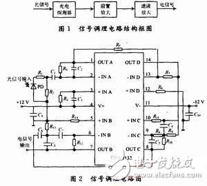
In Figure 2, a 1μF capacitor C9, C10 is connected between the power supply voltage input terminal and ground to filter out the interference caused by the power supply.
2 Photodetector and its working mode selection
2.1 Photodetector selection
A photodetector is a device that detects an optical signal by a photoelectric effect. The choice of photodetector should be considered; the photoelectric sensitivity requirement is high enough; the signal-to-noise ratio is high; the corresponding peak wavelength should match the emission wavelength of the light-emitting device, the low-loss window of the fiber; the response speed is fast; the output photocurrent-illuminance characteristic curve is linear Good.
There are many types of photodetectors. In interferometric fiber optic sensors, photodetectors typically employ PIN junction and avalanche photodiodes.
PIN photodiode has high response frequency, fast response, low supply voltage and stable operation. Avalanche diodes have high sensitivity and fast response, but require hundreds of volts of operating voltage, and the gain causes noise, which is prone to current distortion. Taking into account the wavelength range measured by the system and the stability of the device in the range of 0 to 40 ° C, the InGaAs PIN photodiode G8371-03 photodiode was decided. The photodiode is also excellent in temperature characteristics and has a better characteristic curve than other photodiodes.
2.2 Photodetector working mode
Photodiodes typically operate in two modes: zero bias operation and reverse bias operation. Figure 3 shows the bias circuit for both photodiodes.
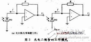
In photovoltaic mode, the photodiode works very accurately linearly; in the light mode, the photodiode can achieve a higher switching speed, but at a sacrifice of a certain linearity. Under reverse bias conditions, there is still a small current (dark current) even without light. There is no dark current at zero bias, and the noise of the diode is basically the thermal noise of the shunt resistor. At the time of reverse bias, shot noise due to conduction becomes an additional source of noise. The sensor signal to be detected for this design is a very weak signal. Trying to avoid noise interference is the primary task, so the design uses photovoltaic mode.
3 preamplifier circuit
3.1 Circuit design
The principle of the preamplifier circuit is shown in Figure 4. The signal input through the PIN photodiode is converted into a voltage signal by I/V conversion, and then the voltage signal is amplified by the intermediate amplifier circuit. Circuit Analysis: The op amp U1A and its peripheral components form an I/V conversion circuit. R1 is to eliminate the glitch in the detector output current, R2 is to prevent the circuit from self-excited and provide DC channel, C1 is DC blocking capacitor, C3 and R4 are used for DC balance and AC compensation. R3 is the feedback resistor and C2 is used to reduce the noise bandwidth to ensure that R3 has the least impact on circuit noise. Since the amplitude-frequency characteristic of the circuit changes after adding the capacitor C2, it is equivalent to a filter. Therefore, when selecting C2, the spectrum of the PIN tube detection signal should be considered at the same time to avoid excessive attenuation or filtering of the useful signal. The inverting amplifier composed of the operational amplifier U1D and its peripheral components R5, R6, and R7 is used as an intermediate amplifying circuit to further amplify the voltage signal.
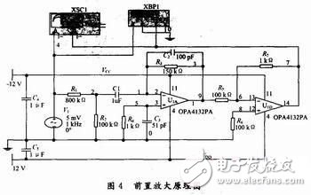
It is also important to integrate the op amp selection in the circuit. It has high requirements on its input resistance, open loop gain, slew rate and gain bandwidth, and noise voltage. The high-speed FET input wideband integrated operational amplifier OPA132 from BB has a very high input impedance; large open-loop gain and gain bandwidth, extremely fast voltage conversion rate and extremely small equivalent noise bandwidth are ideal. Set up an integrated circuit for amplification. In this paper, the OPA132's four op amp form OPA4132 is selected in the circuit, which greatly reduces the complexity of the circuit volume and configuration, and reduces the noise introduction.
3.2 Circuit Simulation
The simulation circuit was built, and the preamplifier of the design was simulated by the two-channel oscilloscope and the Bode plotter in the simulation software MulTIsim 10. The simulation results shown in Fig. 5 were obtained. It can be seen from Fig. 5 that after the preamplifier circuit, the output signal is amplified by about 2 & TImes; 103 times compared with the input signal, and substantially no distortion.
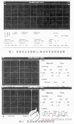
Figure 6 shows the amplitude-frequency characteristic of the circuit. It can be seen that the preamplifier circuit has a certain suppression effect on the high frequency, and mainly enlarges the low frequency weak signal. In the middle horizontal line of the curve, it can be clearly seen that the gain of the circuit is 65.284 dB. The upper limit frequency fH=9.501 kHz can be obtained by dragging the reading axis with the mouse, the lower limit frequency fL=194.486 Hz, and the bandwidth B=fH-fL= 9.306 kHz.
4 band pass filter circuit
4.1 Filter design
In order to make the detection circuit have a good signal to noise ratio, it is also necessary to further process the signal with a band pass filter. The design incorporates a bandpass filter circuit after the preamplifier circuit to remove noise outside the wanted signal band, including ambient noise and noise introduced by the preamplifier. Due to the low frequency of the signal caused by vibration, the effective frequency of the signal is experimentally determined to be between 2 and 5 kHz. The design requires a filter with a center frequency of 2 kHz, a bandwidth of 500 Hz to 8 kHz, and a gain of G=2.
5 Conclusion
In this paper, the signal conditioning circuit is designed for the characteristics of the input signal of the interference fiber sensor, and the simulation is carried out with the software MulTIsim 10. After simulation, the parameters basically met the design requirements. The signal conditioning circuit has a simple structure and good performance, and has certain utility value for the practical application of the interference optical fiber disturbance sensor.
Led Surface Panel Light,Direct-Lit Led Panel Lamp,Direct-Lit Led Panel Light,Surface Mounted Panel Light
Changxing Fanya Lighting Co.,Ltd , https://www.fyledlights.com