Introduction to the design of piezoelectric wafer keyboard

Are you still worried that your keyboard is "fear of water"? The piezoelectric disc keyboard is here to solve all your concerns. This innovative design uses a piezoelectric disc as both a sensor and a buzzer, detecting even the slightest pressure on a 0.4mm-thick stainless steel plate. It’s not only waterproof but also highly resistant to vandalism. In this article, we’ll walk you through the design of this unique piezoelectric wafer keyboard. 
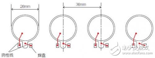
At the heart of the sensor is a piezoelectric disc, commonly used as a buzzer. For this project, we’ve chosen Murata’s 7BB-35-3 model, which has an outer diameter of 35mm and a sensing area of about 20mm. The PCB features electronic components and round holes that allow the ceramic material to move freely. To secure the disc in place, a 3mm thick self-adhesive foam rubber is used, and the assembly is clamped to the back of the front panel with appropriate pressure. 
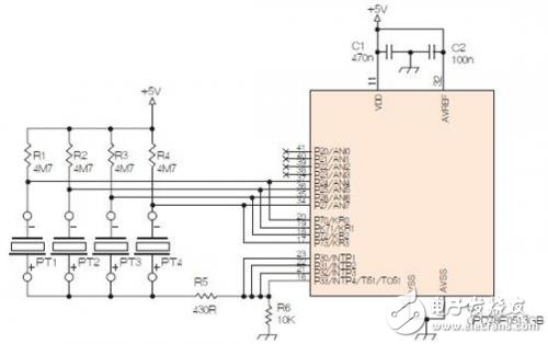
Below is the PCB layout and opening for reference:

Design of piezoelectric disc type waterproof and tamper-proof keyboard

When you press the outer panel with your finger, the steel (or other material) slightly deforms, transferring the pressure through the rubber to the piezoelectric disc. This small amount of pressure generates a detectable voltage, which the microprocessor can sense. At that point, the processor activates all the discs as buzzers, producing a beep as a response. In this example, four buttons are used, and the microcontroller is the uPD78F0513 from Renesas Technology (formerly NEC). However, other microcontrollers could also be used depending on the application. The smaller electrode of the piezoelectric wafer is connected to the ADC input of the microcontroller, while the larger electrodes are connected to several parallel port bits. These ports are initially set to low, and the smaller electrode is connected to a high-impedance state. When the wafer is pressed, the voltage at the ADC input drops, triggering the microcontroller to process the input. Here's a schematic of the piezoelectric keyboard/buzzer:

Design of piezoelectric disc type waterproof and tamper-proof keyboard

At startup, P3 is set to low, and P7 is high. The piezoelectric wafer charges quickly, with a capacitance of approximately 30nF. After a few microseconds, P7 is switched to a high-impedance input. The program continuously scans the ADC input. Due to the large capacitance of the wafer, the voltage changes slowly, so fast scanning isn’t necessary. In this specific application, the voltage is measured every 1ms, meaning each wafer is checked every 4ms. When the input voltage drops below a preset threshold due to a button press, the controller processes the signal and uses the wafers as buzzers. With a 0.4mm thick steel plate, a threshold of 1.5V below the 5V supply is sufficient for good sensitivity. If a thicker front panel is used, there is still room to increase sensitivity further. To produce a beep, P7 is set to a low-impedance output, and P3 is set to the opposite polarity, creating a square wave at the piezo’s resonant frequency (2800Hz in this case). The beep lasts for 250ms, and the current is limited by resistor R5. After the beep, P3 returns to 0, and P7 briefly goes high again to recharge the wafer.

Coils

Car Phone Wireless Charging Coil,Circuit Board Induction Coils,Intersection Induction Coils,Induction Coil Set

Shenzhen Sichuangge Magneto-electric Co. , Ltd , https://www.scginductor.com