Application of phase shift trigger chip TCA785 in the circumferential current control of magnetic particle flaw detector
Application of phase shift trigger chip TCA785 in the circumferential current control of magnetic particle flaw detector
0 Overview
Magnetic particle flaw detector has been widely used in aviation, machinery, automobile, internal combustion engine, railway, ship parking and other departments due to its relatively simple structure, fast detection speed, low cost, and low environmental pollution. Because the demagnetization of some wheel-pair fluorescent magnetic particle flaw detectors is unstable, it is necessary to improve the thyristor voltage regulation scheme in the circumferential current circuit control system. At present, in the magnetic particle flaw detection equipment used in production, the circumferential current is mostly composed of two thyristors connected in reverse parallel to form a voltage regulating circuit. This article gives a method of using TCA785 phase-shifting trigger to control the voltage of SCR.
1 SCR voltage regulation principle and trigger mode
SCR has the advantages of small size, light weight, high withstand voltage, low price, sensitive control and long service life. It enables the application of semiconductor devices from the field of weak electricity to the field of strong electricity, and is widely used in rectification, inverter and adjustment In high-power electronic circuits. A thyristor is an active switching device. It is normally kept in a non-conducting state until a small control signal triggers it (or "ignition") to make it conductive, and once it is conductive, even if it is evacuated Trigger signal, it also keeps on, and to turn it off, you can add a reverse voltage between its anode and cathode or reduce the current flowing through the thyristor diode below a certain threshold. Most of the magnetic circuit of the magnetic particle flaw detector adopts thyristor voltage regulation to control the circumferential magnetizing current.
1.1 The principle of SCR voltage regulation
The conditions for the thyristor to turn on and off are: when the anode potential is higher than the cathode potential and the control electrode has sufficient forward voltage and current, it can be turned off to turn on; and the anode potential is higher than the cathode potential and When the anode current is greater than the sustain current, the thyristor can be kept on; when the anode potential is lower than the cathode potential or the anode current is less than the sustain current, the thyristor changes from on to off.
Generating a trigger pulse is one of the necessary conditions for the thyristor to turn on, and its quality will directly affect the working condition and performance of the thyristor. Therefore, the reliability of the trigger circuit that generates the trigger signal is directly related to the quality of the thyristor voltage regulator.
1.2 Trigger mode of SCR
There are usually two trigger modes for implementing AC voltage regulation with thyristors, namely zero-cross trigger mode and phase shift trigger mode.
Zero-crossing triggering triggers the thyristor to turn on near the zero point of the power supply voltage, and realizes AC voltage regulation by changing the number of cycles of the thyristor turning on within the set period. The thyristor fixed cycle zero-crossing trigger waveform is shown in Figure 1. In Figure 1, Tc is the period of the control signal, tl and t2 are the on and off times of the thyristor, and Tc = t1 + t2. This circuit realizes voltage regulation by changing the on-off time of the thyristor, that is, changing the on-off frequency. Generally, the control circuit first connects the load and the input voltage U for t1 seconds (n cycles) through the period Tc, and then disconnects t2 seconds (m cycles), that is, the output voltage of the load is adjusted by changing the on-off time . 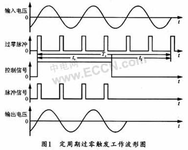
Phase shifting triggers voltage regulation by changing the conduction angle. Figure 2 shows the conduction conditions when the phase-shifting trigger angle of the trigger pulse is 45 °, 90 °, and 135 °. From Figure 2, it can be seen that the voltage across the load changes with the change of the phase-shifting trigger angle. 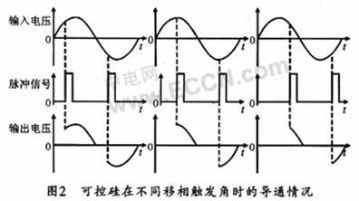
The phase-shift trigger has a part that keeps on and off in each positive or negative cycle of the thyristor, that is, the output is continuously adjustable, so it can adapt to various loads, but during the control process, it will cause electromagnetic interference to the power grid. According to the nature of the load, the use conditions and the surrounding environment, this design selects the phase-shift trigger as the trigger control mode of the thyristor.
2 Design of thyristor phase shift trigger circuit
With the improvement of integrated circuit manufacturing technology, integrated flip-flops overcome the shortcomings of discrete component flip-flops, and thus are widely used. This article uses the integrated trigger circuit TCA785 to transform existing equipment to improve equipment performance.
2.1 Introduction to TCA785 phase shift trigger
The TCA785 phase-shifting trigger is a single-chip phase-shifting trigger. It is a dual-in-line 16-pin large-scale integrated circuit. Compared with other chips, the TCA785 has a good output pulse uniformity, a wide phase shift range, and a wide output pulse. Man-made adjustment and other advantages, so the scope of application is more extensive.
2.2 The working principle of TCA785
The principle of TCA785 is shown in Figure 3, where pin 11 is connected to the phase shift control level Vn, pin 6 is connected to the modulation signal, pin 5 is connected to the synchronization signal, pin 12 is grounded through the capacitor, and pins 9 and 10 are respectively connected to the sawtooth slope resistor and capacitor , Pins 15 and 14 are pulse output terminals Q1 and Q2. 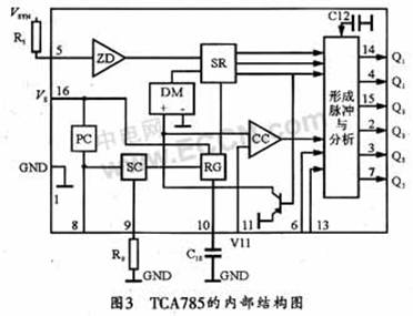
The synchronous voltage VSYNC passes through the resistor R5 to the zero phase detector ZD. When ZD detects its zero crossing, it can be sent to the synchronous register SR and the SR controls the sawtooth generator RG. The capacitor C10 of RG is determined by the resistor R9. The source SC is charged. When the sawtooth voltage V10 of the capacitor C10 is greater than the phase shift control voltage V11, a pulse signal is generated to the output logic unit, and a trigger pulse is generated at pin 14 (Q1) and pin 15 (Q2). It can be seen that the phase shift of the trigger pulse is controlled by the magnitude of the phase shift control voltage V11, the trigger pulses Q1 and Q2 can be phase shifted within the range of 0 ° to 180 °, and the output pulses of the pins 14 and 15 are 180 ° out of phase.
The main pin waveform of TCA785 is shown in Figure 4. Among them, 5 feet are external synchronization signal terminals, which are used to detect the zero crossing of the AC voltage. Pin 10 is a synchronous sawtooth wave generated on-chip. The maximum and minimum slopes are determined by the external resistance and capacitance of pins 9 and 10. By comparing with the control voltage of the 11th pin, synchronized pulse signals can be output on the 15th and 14th pins. Therefore, the phase shift control can be realized by changing the control voltage of the 11th pin. The width of the pulse is determined by the external capacitance value of the 12-pin. When the drive mode of the double narrow pulse is selected, the 12-pin should be connected with a 150pF capacitor. In fact, a pulse width of tens of microseconds can normally turn on the thyristor. 
2.3 Design of thyristor phase-shift trigger circuit
The control object of this control system is CJW-4000 wheel and wheel magnetic particle flaw detector, which is composed of power control system, inlet / outlet wheel system, spray magnetization system, fluorescent lamp system, magnetic separation liquid spray recovery system and dark room. The equipment control circuit adopts PLC centralized control.
The thyristor phase-shifting trigger circuit of the wheel-pair fluorescent magnetic particle flaw detector is shown in FIG. 5. This circuit uses the Q1 and 02 output of TCA785 (ie, the output of pins 14 and 15) to directly trigger the thyristor in the positive and negative half cycles of the AC power supply respectively. The phase shift control voltage U11 comes from the external DC power supply V1 (here +15 V is used) ), When continuously changing within its effective range (0.2 V to V1-2 V), the phases of the pulse outputs Q1 and Q2 can be shifted within the range of 0 ° to 180 °. 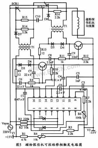
Since the signals coming from the synchronous transformer are sinusoidal signals, and the TCA785 uses the principle of detecting zero crossing to achieve synchronization, therefore, if the amplitude of the sine wave is too small, then it cannot provide a clear zero crossing point, and the electromagnetic interference is also It may lead to the error of zero-crossing detection. However, if the amplitude of the sine wave is too large, it will exceed the synchronous voltage input range of the chip, so the synchronous signal should be shaped into a square wave. As shown in Figure 5, between pin 1 (ground) and pin 5 is to use anti-parallel limiting diode (tube voltage drop is about 1 V) to change the sine wave into a square wave. After pin 5 is connected to a 220 kΩ resistor, it can be directly connected to a 220 V AC synchronous voltage signal to detect the zero-crossing point of the AC voltage. At the same time, two positive and negative parallel limiting diodes are connected to the ground to start Protective effects.
Pin 12 is the pulse width control end of output pulses Q1 and Q2. Its application range is 150 ~ 4700 pF.
Pin 6 is the pulse signal disable terminal. The +15 V power supply can be connected via a resistor R2 with a resistance of 10 kΩ. When the voltage of this terminal is less than 2.5 V, the output pulse is blocked; and when the voltage of this terminal is greater than 4 V, the blocking function does not work. Therefore, this pin can be used as the thyristor overcurrent and overheat protection of the main circuit.
Pin 10 is the maximum and minimum slope of the synchronous sawtooth wave generated by the chip is determined by the external resistance and capacitance of pins 9 and 10, and then by comparing with the control voltage of pin 11, it can output synchronous pulses at pins 15 and 14. In order to change the control voltage of 11 feet, thus realize the phase shift control. Pin 11 can be connected to a +15 V power supply through a capacitor.
3 Problems that should be paid attention to in the application of TCA785
The TCA785 phase shift trigger uses a negative logic working mode, that is, the control voltage increases, the control angle of the output pulse increases, and the conduction angle of the thyristor decreases. This should be noted in the application.
In addition, the anti-parallel limiting diode is generally used between the pin 1 and pin 5 of the TCA785 to change the 220 V alternating current connected to the pin 5 into a square wave, thereby providing a clear zero-crossing signal to the TCA785.
If the trigger circuit is used for circumferential current charging and demagnetization, a rectifier bridge should be added after the AC current output by the thyristor to change the current to DC, and then connected to the circumferential coil of the magnetic particle flaw detector.
4 Conclusion
In this paper, the thyristor phase-shifting trigger circuit with TCA785 as the core can effectively control the charging and demagnetizing of the circumferential magnetic field of the fluorescent magnetic particle flaw detector of the wheel and wheel. If there is a crack, the magnetic field of the wheelset after the detection can be reduced to within the standard, thereby improving product quality. The circuit design is relatively simple and reliable, and can effectively guarantee the detection quality of the flaw detector.
Grinder Machine,Surface Grinding Machine,Grinding Equipment,Tool Grinding Machine
Hunan Furui Mechanical and Electrical Equipment Manufacturing Co., Ltd. , https://www.thresher.nl