Broadcom BroadR-Reach Automotive Ethernet Solution
Since its inception in 2003, the AUTOSAR (Automotive Open Systems Architecture) Alliance has been working to change the way in-vehicle networks and electronic control units (ECUs) are designed. AUTOSAR proposes an industry-standard in-vehicle network design methodology that enables the industry to integrate, exchange and transmit functions, data and information within the automotive network. This standard greatly facilitates collaboration between automotive original equipment manufacturers (OEMs) and their Tier 1 suppliers, enabling them to exchange design information in a consistent, clear and machine-readable format.
This article refers to the address: http://
Different parts of a car have different requirements for safety and performance, and the in-vehicle network that supports them must have predictable safety. As automotive technology continues to evolve, a range of bus technologies are available to connect up to 100 different ECUs in luxury cars. These bus technologies typically include LIN, CAN, FlexRay, MOST, and Ethernet-based architectures. If it is impossible to manually manage thousands of information and interactions between these ECUs, automotive designers must use automated design and synthesis tools to predict network performance and adjust vehicle functionality.
Car data bus
A typical modern car will be equipped with various buses and protocols and select the right network from LIN, CAN, FlexRay, MOST and Ethernet. Multimedia/audio-visual signals and automotive surround camera systems require higher data rates, so car manufacturers and OEMs choose to replace MOST with Ethernet on network solutions. But for many standard automotive functions, the bandwidth provided by LIN and CAN And performance is enough.
In the automotive architecture, the ECUs are grouped together to form a "cluster" that is connected by a communication "gateway." Clusters usually share the same type of bus, so to achieve high reliability, high rate standards, FlexRay network is required, but the door lock ECU that requires less high can be responsible for CAN or LIN. ECU gateways often have to connect different types of signals and perform mapping and conversion functions between different bus architectures. The automotive industry places strong demands on increasing safety and compliance with standards such as ISO26262, which in turn improves the performance of in-vehicle networks while reducing manufacturing and component costs. Evolving network standards can adapt to ever-increasing data rates, and automotive cables have reached a safe and low-cost goal. The characteristics and applications of typical automotive network solutions are shown in Table 1.
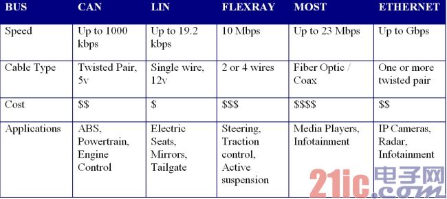
Table 1: Automotive network bus.
FlexRay network:
The FlexRay protocol is more deterministic than CAN. FlexRay is a "time-triggered" protocol that offers different options for information to be sent to the target address in a precise time frame - accurate to 1μs. FlexRay information can be up to 254 bytes, so it needs to be in the ECU The amount of complex information exchanged between them is large. Compared to CAN, FlexRay has a higher data transfer rate. Since the timing is predetermined, the information needs to be planned in advance and is generally pre-configured or designed by the automotive OEM or Tier 1 supplier partner. In a network using the CAN protocol, the ECU node only needs to know the correct baud rate when communicating, but the ECU node on the FlexRay network must know how the various parts of the network are configured and connected when communicating. Checking and verifying the timing of the FlexRay network is time consuming – so automated timing analysis and packetization of information into time frames can reduce errors and design cycle times.
Automotive communication matrix synthesis
The overall definition of automotive network scheduling is typically stored in a "communication matrix" that is part of the central gateway ECU. The design tool solution developed by Mentor can be used to automatically synthesize this database and package all the different information into frames in the correct order.
The AUTOSAR signal information is combined into Protocol Data Units (PDUs) which are then combined into a transmission frame. For CAN and LIN frames, there is one PDU per frame, but one FlexRay frame may contain multiple signal PDUs.
In the FlexRay architecture, timing is deterministic, and the main uncertainty facing designers is frame packing and transmission order. Automotive OEMs and designers invest a lot of time in testing all possible situations in a car to determine worst-case behavior and ensure a greater safety margin for information transmission. This means that in order to ensure a high level of timing safety, the full capacity of the data bus cannot be taken up. The synthesis tool optimizes frame utilization by finding signals with similar paths and timing requirements for packing and scheduling in similar frame time gaps. When using Mentor's timing synthesis tool, the design inputs will include signal and PDU definitions, frame priority, and specific OEM design decisions regarding possible signal paths. Take these into account when generating a complete timing system.
There is a problem in installing a fully defined communication system, that is, it is difficult to have architectural changes in the future, and may require a complete redesign of the network, but the advantages of high speed and certainty of transmission make this method to FlexRay. The application creates great appeal and ensures the car's very high safety requirements. Re-establishing a more advanced communication system with this synthesis tool can shorten the repair cycle.
FlexRay has begun to take advantage of single-channel high-speed powertrain, driver assistance and automotive electronics for increased comfort. In the BMW X5, FlexRay is used in suspension control, allowing engineers and developers to use this dual-communication channel and bus monitoring to apply this fault-tolerant deterministic protocol to safe driving functions. A gradual adaptation process reduces the associated risks.
In the development of FlexRay applications, design engineers can build a robust network topology in five basic steps.
Step 1: First, you must define the number of nodes on the vehicle chassis and their assumed positions, and then determine the cable length required to implement a passive bus without stubs (a topology known as "daisy chain"). The terminal is the cable terminal, as shown in Figure 1. If the cable length is less than 10 meters, the topology is completed and it is considered to be usable for series production.
Step 2: Once the cable length is found to be greater than 10 meters, the “active star†topology should be considered (see Figure 2). If the cable length exceeds 20 meters, the active star must be introduced. The simplest active star has only two branches, and the harness is two electrical decoupling components. Because the active star is enhanced by NXP's TJA1080 transceiver (the first of its kind for the BMW X5), the total number of transceivers required has only increased by one.
Step 3: If the application can continue to work after a collision accident, the collision sensitive nodes of the system should be distributed on different branches (see Figure 3). In this way, once the cable is squeezed or clamped to a differential voltage, only the data transmission of the affected branch is interrupted, but the active star will ensure that communication to other branches in the network is not affected.
figure 1
figure 2
image 3
Step 4: Due to the presence of resonance, nodes or wiring exposed to very harsh RF fields should also be distributed to different branches (see Figure 4). The RF induced current is transferred to the ground using a terminal (FlexRay Electrical Physical Layer Specification v2.1 Revision B) at each end of the cable. This results in a lower common-mode voltage on the cable without affecting the nodes connected to other branches. Therefore, the jitter in the received data stream can be controlled within a reasonable range.
Figure 4
Step 5: To ensure that there is always a suitable terminal at both ends of the cable (see Figure 5), the end node of the trunk cable should not be an optional node. The electrical position of the node along the cable must not cause the cable length to exceed 10 meters. On non-optional nodes, a short stub ("1 meter") can be introduced. Even with greater flexibility, the active star does not have to be at the cable end.
Figure 5
Verification and optimization
Following these five steps helps build a FlexRay topology that is robust in terms of electronic properties. Simulations are recommended to further validate and optimize the defined topology. The Monte-Carlo simulation is used to estimate manufacturing tolerances for wire harnesses, yield ranges, and temperatures that depend on the transceiver and active star.
In addition, the FlexRay Consortium has introduced a sophisticated cable model that encompasses the skin effect of the harness. While supporting automotive manufacturers to introduce FlexRay, NXP is also constantly improving its expertise in FlexRay topology simulation.
More information on terminals, cables and connectors for FlexRay applications can be found in FlexRay Electrical Physical Layer Specification v2.1 Revision B. Electrical Physical Layer Application Note v2.1 Revision B gives some suggestions for topology design. Both specifications are available on the FlexRay Alliance website. For technical details of the TJA1080 FlexRay transceiver, check out the NXP website.
Electronic systems have been used in automobiles for decades, and they have greatly improved the safety, energy saving and environmental performance of automobiles. With the deepening of research, many systems need to share and exchange information. In order to save cables, a distributed embedded system that relies on communication is formed. Currently, 90% of the world's systems use CAN bus-based systems. FlexRay is the de facto standard for next-generation communication protocols, and how functional security is critical.
1 Communication failure causing system security risks
There are five manifestations of communication failures, the first being errors in the range. The second type is the error that causes time domain, which is the part of industry that is different from civilian use. If a message cannot be delivered before the scheduled time limit, it loses its practical significance. For example, sensor messages related to airbag detonation cannot be delivered within a few ms, causing safety problems. There is a third type of error in multicast or broadcast communication: data integrity error (Byzantine error), that is, the results received by each node are inconsistent. It causes systemic failures, and the strategy to deal with must consider all relevant nodes at the same time. The fourth type is system crash. In addition to hardware failure, there is also interference or software, such as babbling idiot to block communication. The fifth type is frame loss, short-term failure, such as recoverable offline or bug-induced equivalent offline state, and small group error.
2 Communication failure rate
In the analysis of the impact of communication failure on system security, the reference provides a method to calculate the length of communication failure based on the possible length of transient interference, and to introduce the system failure rate under the assumed communication failure rate. In this example, the interval of the electric field exceeding 100 V/m on the road section may cause communication failure, the failure rate is approximately 5×10⁻³, the vehicle speed is 90 km/h, and the identified possible failure time is about 74 s. The communication is in the period of 6 ms, and the frame loss for 7 consecutive cycles is regarded as system failure. Under this condition, the system failure rate is 1.640 9×10⁻¹⁰, which is considered to meet the security requirements of SIL4. This analysis method is effective, but the assumptions are too many, for example, the bit error rate has a large change interval; the change of the frame length affects the failure rate of one transmission; the assumption of the interference duration; the continuous loss of 7 frames is also For the application occasion, the loss of control of the vehicle of 90 km/h for 42 ms has a distance of about 1 m for the braking system. I am afraid that the consequences of the impact are completely different. It is also assumed that SIL4 is completely allocated to the communication, and the CPU is Part of the software-related failure rate is negligible. Today, the software is getting bigger and bigger, this assumption is unreasonable. On the other hand, when determining the system failure rate, other forms of communication failure should also be considered. For example, the time when a small group is wrong to conflict depends on the relative clock drift. The more accurate, the longer the time between failures, the longer the failure time. In the reference, it took 300 ms to artificially create a small group to find the conflict, far exceeding the above 42 ms. Therefore, the general discussion of system security articles separately stipulates that the communication failure rate is 1/100 of the corresponding security level failure rate.
3 Factors affecting communication failure rate
The functional safety level is related to the coverage of fault detection. If some faults are not detected (not recognized or can not be achieved), of course, the failure scenario cannot be counted, and the division of the safety level is wrong.
The reference introduces the concept of SFF (Safety Failure Fraction): failure is divided into hazard-based failures and safety failures, which are divided into two types: detectable and undetected. The safety failure ratio SFF is the share of the total failure that can be detected as a hazard failure and a safety failure. Diagnostic Coverage (DC) is the share of hazard failures that can be detected as a total hazard failure. It can be derived that SFF has a linear relationship with DC. SFF is related to SIL. The SIL rating of IEC61508 is related to SFF. SIL3 can tolerate one fault when SFF accounts for 90%~99%. Therefore, DC also determines the SIL level that can be achieved. According to the article, the probability of transient faults is two orders of magnitude larger than the probability of hardware failure. Therefore, it can be roughly inferred that the coverage of transient fault diagnosis should reach 90%~99%. Hazard failure may be caused by communication failure, and diagnostic coverage becomes an important part of evaluating communication protocols.
In the communication, because the CRC has missed detection, this is an obvious diagnosis of the uncovered area, and the diagnosis of the uncovered rate is equivalent to the missed frame miss detection rate, such as the CAN frame miss detection.
A value domain error or a time domain error occurs in communication and a frame loss is a hazard that can be diagnosed (this is the main object of this analysis). False mistakes, Byzantine mistakes, etc. should be undetected hazards. When a small group error occurs, both frame loss and Byzantine error may occur. The equivalent off-line failure of CAN is also a hazard failure caused by an uncovered diagnosis. It is still difficult to calculate the proportion of hazard failures caused by these uncovered diagnoses to total hazard failures, because it is difficult to determine the probability of failure model. However, qualitatively, only the diagnosis of counterfeiting, Byzantine error and small group mistakes can be made to improve the diagnostic coverage (increased SIL level).
Regarding the shortcomings or weaknesses of FlexRay, the reference mentions the difficulty of physical layer connection, affecting signal integrity. In fact, it is easier to use active star type, but this brings cost improvement; cycle design constraints are many, with It is difficult; synchronization and startup node configuration is related to fault tolerance, which is a challenge; due to limited resources, it is difficult to upgrade and evolve (not like the composability advantage of the time-triggered protocol as before - the author's note). The reference describes the possibility of generating separate clock synchronization small groups in FlexRay, which means that although each node is communicating, there is no effective communication between the two groups, which is a fault condition. The solution is to use 3 cold start nodes and 3 synchronous nodes, but this contradicts the requirement of time synchronization fault tolerance. There is also the need to fill the schedule to avoid the formation of small groups, which is also in conflict with the requirement to leave room for future upgrades. In short, there is no complete solution. Then there is a clock that may produce a drift in the same direction, and the difference between the application clock causes the frame to fail to be ready or the cover causes a missing frame.
Features
1. In the cable laying process, it can support the cable and change the sliding friction into rolling friction between cable and support, which means it can reduce pulling force.
2. Straight pulling roller is used in the straight line segment of cable laying. Generally put one roller every 2-3 meter.
3, Corner pulling roller is used in the turning point of cable laying. The amount of corner pulling roller in the turning point is determined by the side pressure and cable bending radius.
Usually used in laying path of cable tray, well head, upper and down slope and control cable.
Notes: When operating, the roller should be fixed in ground or other supports.

Cable Roller,Corner Roller,Hoop Rollers,Cable Guide Rollers
NINGBO BEILUN TIAOYUE MACHINE CO., LTD. , https://www.spool-manufacturer.com