The working principle of electromagnetic flowmeter -- I will learn it, let's take a look.
Introduction: This article explores the working principle of an electromagnetic flowmeter. At first, you might not think of it as a "flow" meter, but this "flow" has nothing to do with traffic. So what exactly is this "flow"? Let's find out together!
1. The Working Principle of Electromagnetic Flowmeter - Concept
An electromagnetic flowmeter is a device that measures the volumetric flow rate of conductive liquids using Faraday’s law of electromagnetic induction. It has been widely used in industrial applications for many years, known for its high accuracy, reliability, and fast response time. The design and quality control system ensure minimal output noise and improved performance. Additionally, the use of linings makes it suitable for more diverse environments.

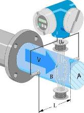
2. The Working Principle of Electromagnetic Flowmeter – Structure and Function
The structure of an electromagnetic flowmeter typically includes a magnetic circuit system, measuring conduit, electrodes, casing, lining, and a converter. Each component plays a crucial role in ensuring accurate and stable measurements.
Magnetic Circuit System: Generates a uniform DC or AC magnetic field.
Measuring Conduit: Allows the conductive liquid to pass through during measurement.
Electrodes: Detect the induced potential signal, which is proportional to the flow rate.
Casing: Made from ferromagnetic material, it covers the excitation coil and protects against external magnetic interference.
Lining: Enhances corrosion resistance and prevents shorting of the induced potential by the metal wall of the tube.
Converter: Amplifies and converts the signal into a standard output while suppressing unwanted interference.
3. The Working Principle of Electromagnetic Flowmeter
The fundamental principle behind an electromagnetic flowmeter is Faraday’s law of electromagnetic induction. In this context, the conductive medium flowing through the pipe is treated similarly to a metal rod moving in a magnetic field. Two coils at the top and bottom generate a constant magnetic field. As the conductive fluid moves through the field, an induced electromotive force (EMF) is generated. The direction of the EMF follows the “Fleming right-hand rule,†and its magnitude can be calculated using the formula:
Ex = B × D × v
Where:
- Ex – Induced potential (in volts)
- B – Magnetic induction (in tesla)
- D – Pipe inner diameter (in meters)
- v – Average flow velocity of the liquid (in meters per second)
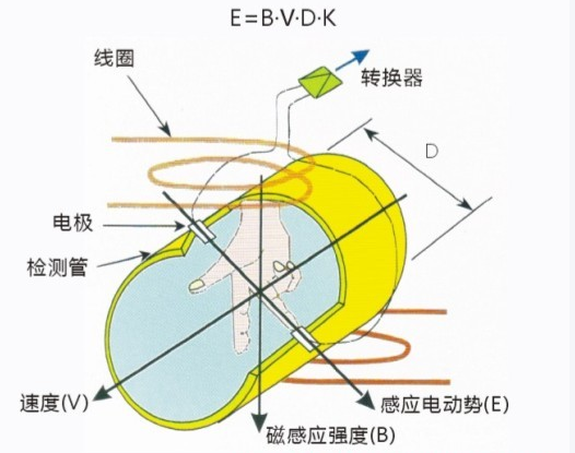
The measuring tube is electrically isolated from the fluid by a non-conductive inner liner (such as rubber or Teflon). An excitation coil is placed above and below the measuring tube, creating a magnetic field when current is applied. Electrodes mounted on the inner walls of the tube detect the induced potential, which is then sent to the converter for processing.
So, we've covered the working principle of the electromagnetic flowmeter. If you found this helpful, here are some related articles you might want to check out:
- 1. Influencing factors and selection/installation of electromagnetic flowmeters
- 2. Usage and management of electromagnetic flowmeters
- 3. How to solve weak signal issues in electromagnetic flowmeters
Electromagnetic Flowmeter
Dual Axis Solar Tracker System
Dual Axis Solar Tracker System,Sun Power Single Axis Solar Tracker,Dual Axis Solar Sun Tracker pv tracker,Pv Solar Tracking System
Hebei Jinbiao Construction Materials Tech Corp., Ltd. , https://www.pvcarportsystem.com