Artificial Intelligence
Detailed translation of the differential circuit to enhance the dynamic range of the system
Differential signals are ideal for circuits that demand high signal-to-noise ratios, strong noise immunity, and minimal second harmonic distortion. These characteristics make them particularly suitable for high-performance ADC drivers and high-fidelity audio processing systems. In an article titled "Multi-Function, Low-Power, Precision Single-Ended to Differential Converter" published in *Analog Dialogue*, a highly improved single-ended to differential circuit is introduced. This design offers a very high input impedance, with a maximum input bias current of just 2 nA, a maximum offset (RTI) of 60 μV, and a maximum offset drift of 0.7 μV/°C. The performance enhancement is achieved by cascading the OP1177 with the AD8476, using a differential gain of 1 within the feedback loop.
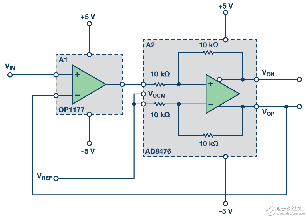
**Figure 1. Improved single-ended to differential circuit**
While this configuration is effective, many applications require a larger output dynamic range, such as signal conditioning for temperature and pressure sensors. If the common-mode voltage can also be adjusted, the circuit becomes more flexible and easier to interface with various ADCs, where the reference voltage determines the full-scale range.
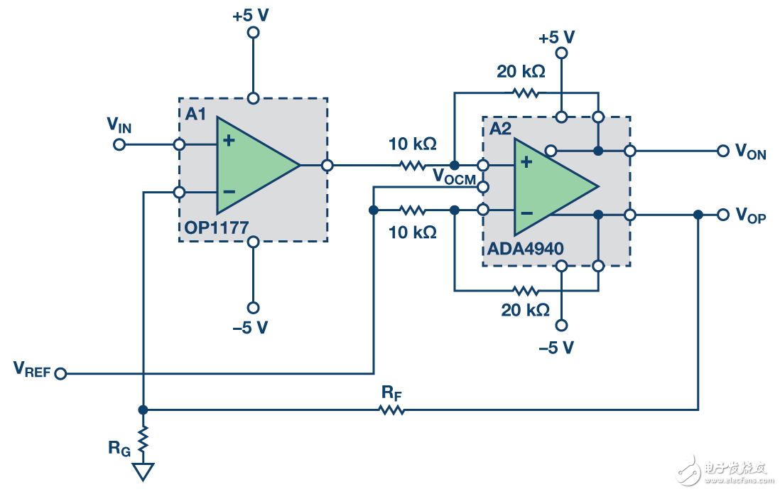
**Figure 2. Single-ended to differential circuit with improved dynamic range**
By setting the internal differential amplifier’s gain to a value greater than one, the output dynamic range of the circuit increases significantly (as shown in Figure 2). The output voltage is calculated as:

In this setup, RG is left open, resulting in a total circuit gain of 2. The output of A1 (OP1177) is given by:

It's important to note that VREF is always added to the output of the OP1177, which limits its output swing. To maximize the dynamic range, VREF is typically set at the midpoint of the power supply. When a differential amplifier with a gain greater than 1, such as the ADA4940 (configured for a gain of 2), is used in the loop, it reduces the output voltage of A1 and lowers the overall differential gain from A2. This helps prevent saturation of the OP1177 output. With a ±5 V power supply, the typical output swing of the OP1177 is about 4.1 V. Therefore, when VREF is set to 0 V, the differential output swing of the circuit in Figure 2 can reach approximately ±8 V. Increasing the A2 gain to 3 further expands the output dynamic range and maximizes the circuit’s output swing. The ADA4950, which supports gains of 1, 2, and 3, is another excellent choice for A2.
Pure Line Interactive UPS,Pure Sine Wave,Dsp Control,Lcd Display
Shenzhen Unitronic Power System Co., Ltd , https://www.unitronicpower.com